Dispensing system and method of controlling the system

a technology of a pouring system and a control system, applied in the direction of liquid handling, packaging goods, transportation and packaging, etc., can solve the problems of reducing the rate at which a beverage can be dispensed, the top pouring system cannot support the dispense rate required at many high-demand venues, and the fobbing or foaming rate is increased. , to achieve the effect of reducing the amount of foaming

Inactive Publication Date: 2011-10-06
MANITOWOC BEVERAGE SYST
View PDF4 Cites 19 Cited by
  • Summary
  • Abstract
  • Description
  • Claims
  • Application Information

AI Technical Summary

Benefits of technology

The invention relates to an improved way that makes it quicker than usual by filling up quickly without getting ridged on any parts like valves when they are being used.

Problems solved by technology

The technical problem addressed by this patented technology relates to improving the efficiency and quality of drink preparation during times when customers require more than one serving size per minute due to factors like fast-fill rates (faster liquid flow) caused by traditional methods involving tapping or fading on bottles). Additionally, current solutions involve adding ice cubes to reduce friction between the container's surface and the customer's hand, but these techniques result only marginally improvement over non-refillable containers. Therefore, there needs a solution that allows users to quickly fill smaller vessels without generating excessive pressure waves.

Method used


Image

  • Dispensing system and method of controlling the system
  • Dispensing system and method of controlling the system
  • Dispensing system and method of controlling the system

Examples


Embodiment Construction

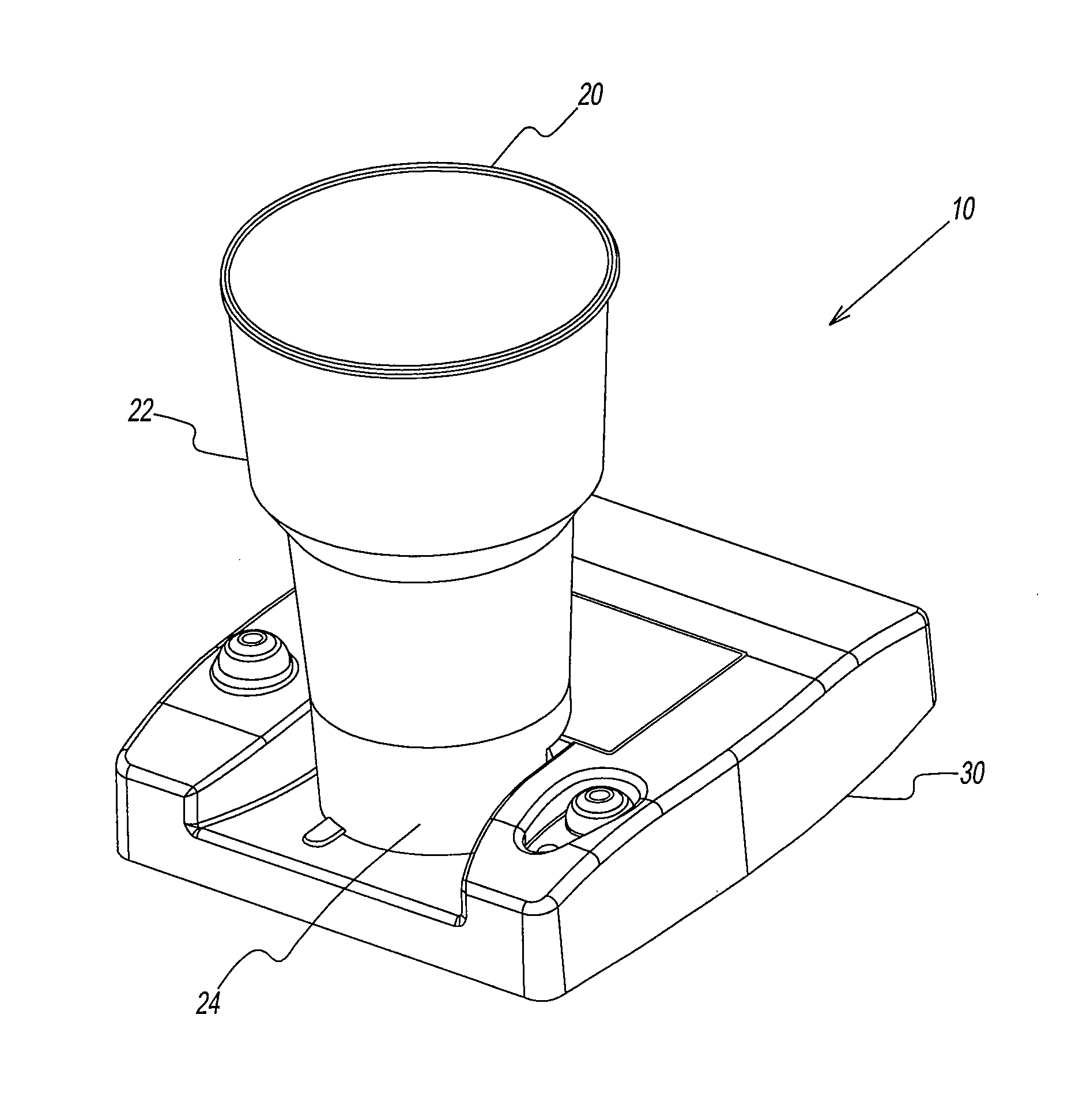
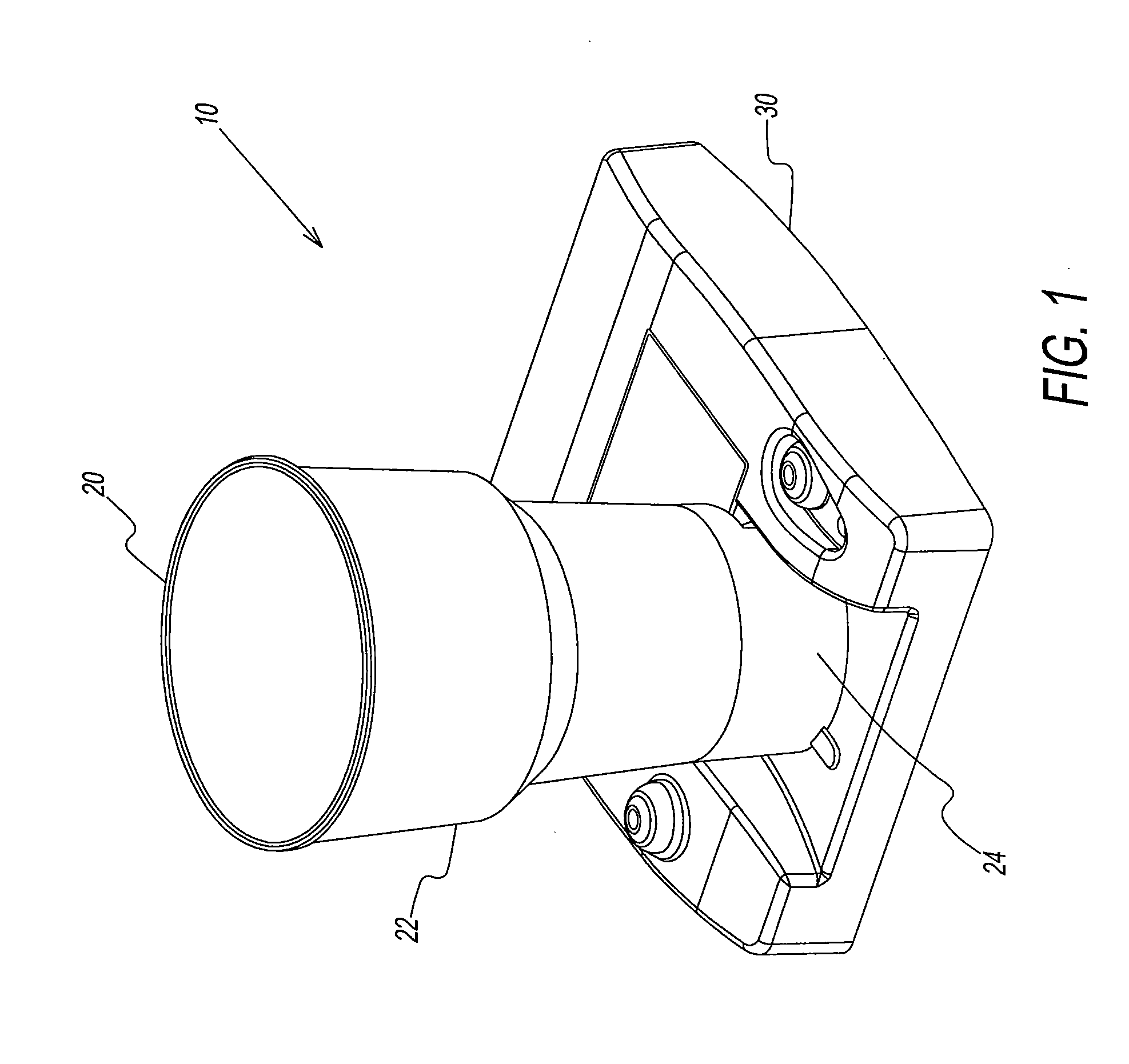
[0067]Referring to the drawings, a beverage dispensing system according to the present disclosure is shown and generally referenced to by numeral 10. Beverage dispensing system 10 includes a vessel 20 that can be removably disposed on a dispenser 30, as shown in FIG. 1. Vessel 20 is designed to contain a liquid received from dispenser 30. Dispenser 30 may contain a control system to regulate the use of dispensing system 10. Beverage dispensing system 10 can effectively control the flow of any type of liquid, carbonated or non-carbonated, such as water, beer, soft drinks, smoothies or other beverage, through dispenser 30 and into vessel 20. Thus, beverage dispenser system 10 can provide for the rapid dispensing of liquids in a very short period of time.

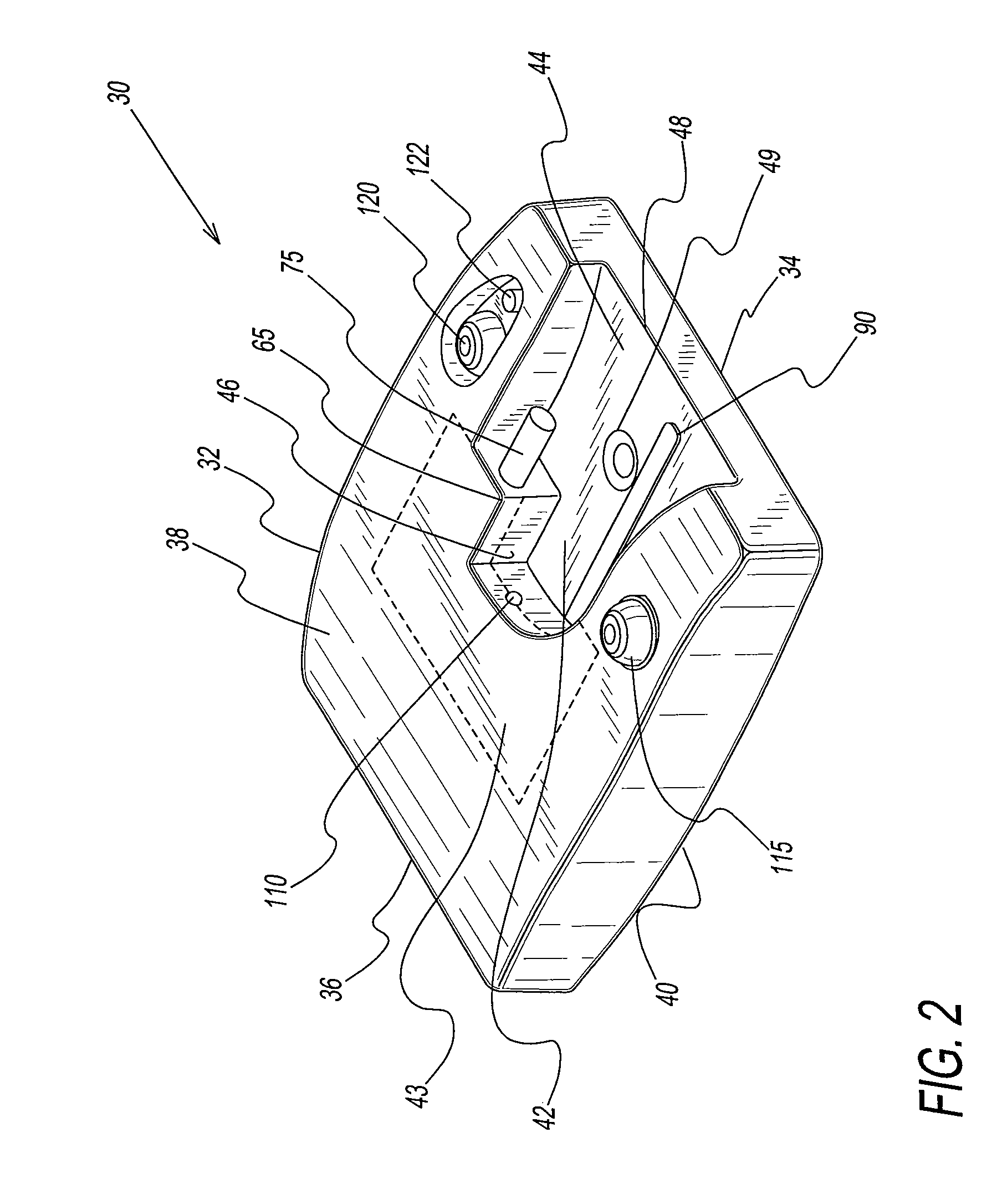
[0068]As shown in FIGS. 2-5, dispenser 30 contains a housing 32 having at least a first end 34, a second end 36, an upper panel 38 and a lower panel 40. Housing 32 can be made out of any durable material, such as, but not limited to plast


PUM

PropertyMeasurementUnit
Timeaaaaaaaaaa
Angleaaaaaaaaaa
Shapeaaaaaaaaaa

Abstract

A dispensing system is provided that includes a vessel having a base portion with an aperture, and a dispenser containing a control system. The dispensing system controls the flow of a liquid into the vessel to provide for a rapid fill.

Description


Claims


Application Information

Patent Timeline
Owner MANITOWOC BEVERAGE SYST
Why Eureka
Try Eureka