Audio signal adjustment device and audio signal adjustment method
a technology of audio signal and adjustment device, which is applied in the direction of gain control, electrical transducers, instruments, etc., can solve the problems of poor sound output, unexpected loud sound, and difficult to hear, and achieve the effect of improving control accuracy
- Summary
- Abstract
- Description
- Claims
- Application Information
AI Technical Summary
Benefits of technology
Problems solved by technology
Method used
Image

Examples
first embodiment
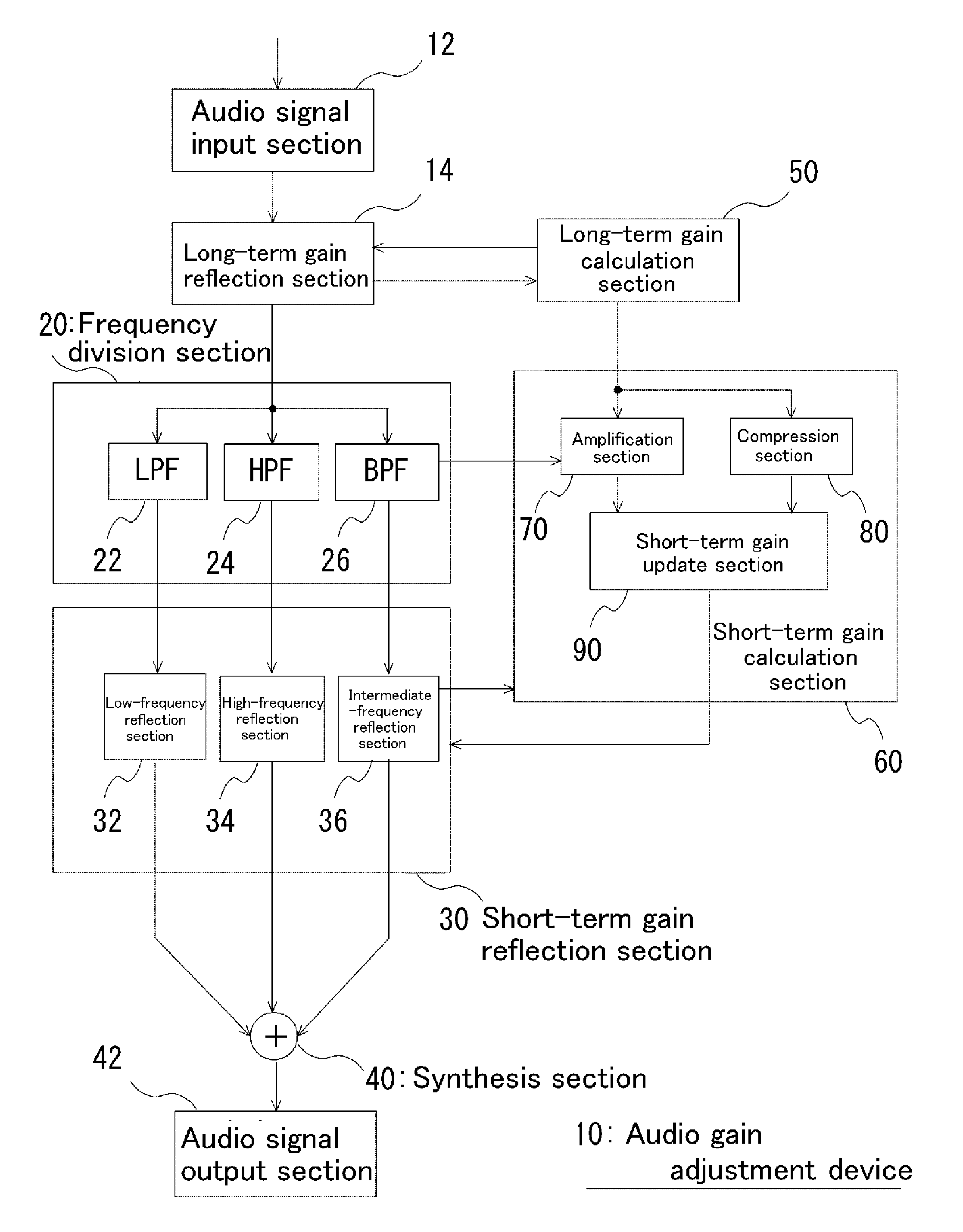
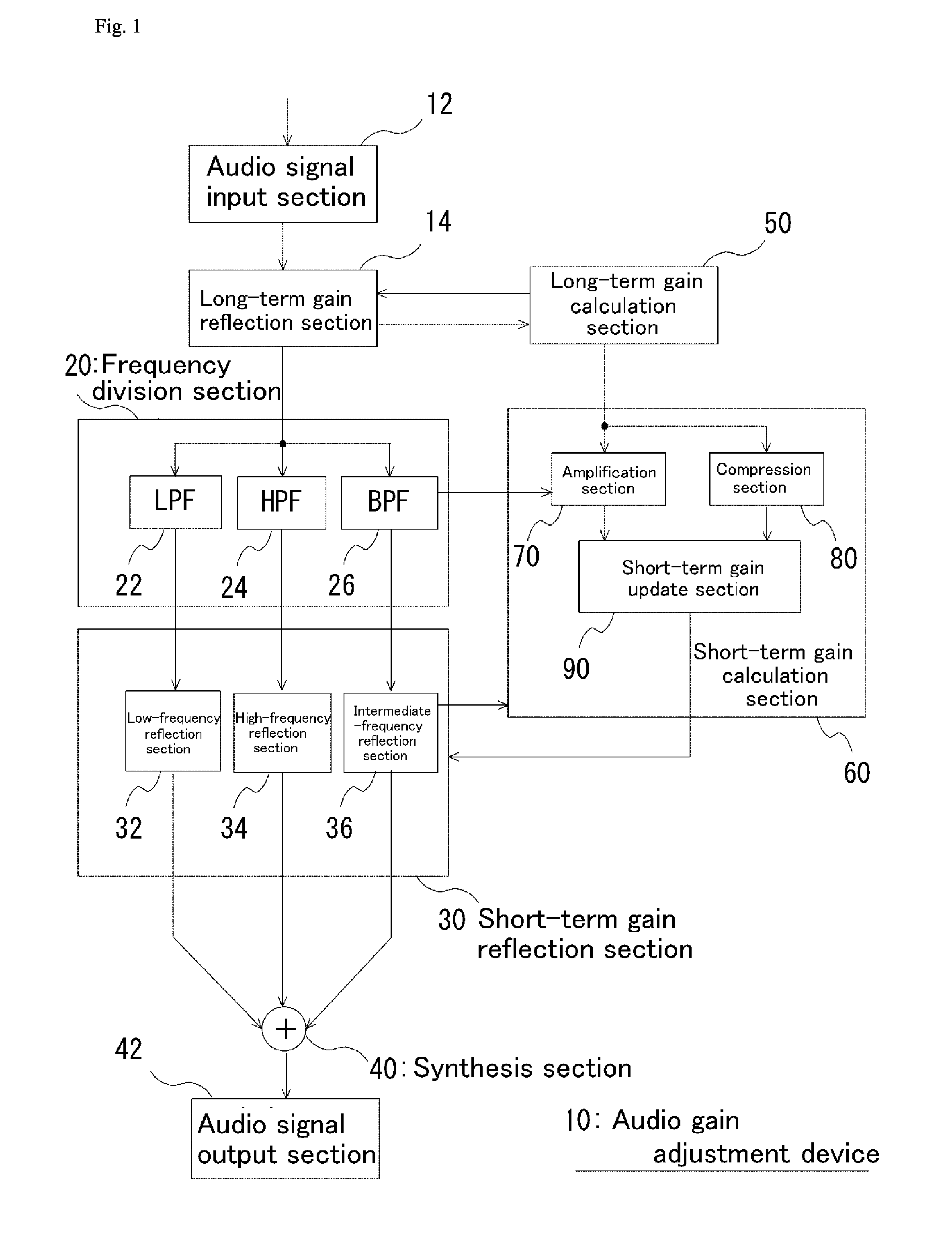
First, an overview will be given of a first embodiment. An audio gain adjustment device 10 described below performs long-term gain adjustment for an input signal, frequency-band divides the resultant output signal using a band division filter, performs short-term gain adjustment for the output signal of each frequency band, and synthesizes the output signals to obtain final output signal.
Long-term gain is obtained by converting a signal within a certain time period that has been subjected to the long-term gain processing into auditory sensation level of a human (hereinafter, referred to as “loudness level”) and comparing the loudness level to a set threshold value (compression threshold value or amplification threshold value). As the loudness level, a level reflecting a loudness curve specified by ITU-R (International Telecommunication Union Radiocommunications Sector) standard may be used. More specifically, by inverting the characteristics represented by the loudness curve, the loudn
second embodiment
The processing performed in the second embodiment differs from that in the first embodiment in some points.
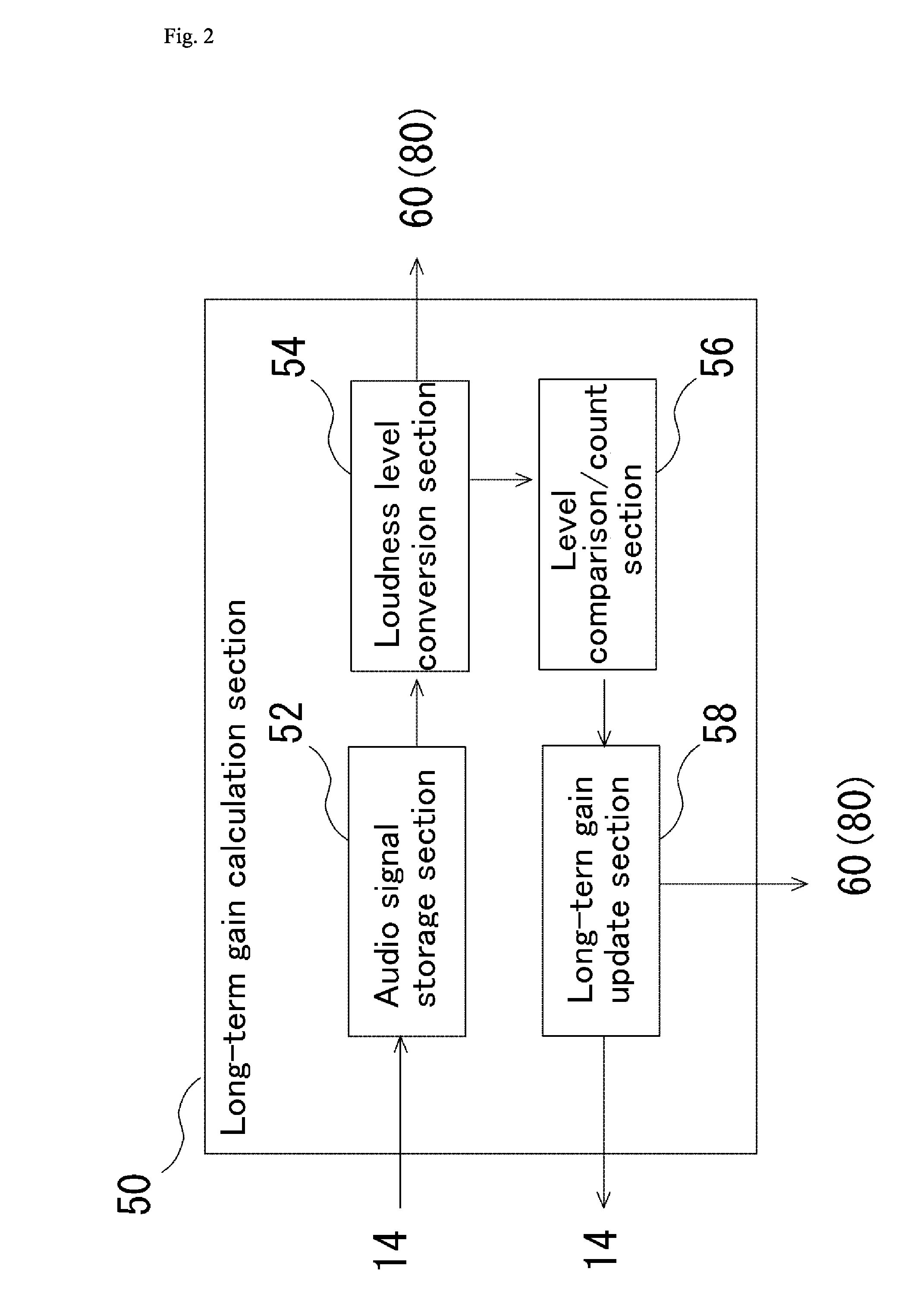
The first different point is the processing performed in the level comparison / count section 56. Specifically, as in the first embodiment, the level comparison / count section 56 has a counter function for long-term gain control and sets the initial value of the counter to “0” and sets the initial value of the long-term gain to “0 dB”. Then, the following processing (1) to (4) are executed. Only the processing of (3) differs from that of the first embodiment.
(1) Increment counter value by “1” when loudness level 2 that has been subjected to long-term gain adjustment exceeds compression threshold value.
(2) Decrement counter value by “1” when loudness level that has been subjected to long-term gain adjustment falls below amplification threshold value.
(3) Count long-term gain in direction going back to initial value when loudness level 2 that has been subjected to long-term gain adj
third embodiment
In the present embodiment, volume control at the time of switching from one input source to another or from one scene from another in one source will be described. There may be a case where the volume level abruptly and significantly changes at the time of switching from one input source to another or at the time of switching from one scene to another in one source in a TV set or audio system. In such a case, a viewer feels uncomfortable or gets surprised accordingly, forcing him or her to frequently adjust the volume. In order to solve such a problem, a technique called ALC (Automatic Level Control) or DRC (Dynamic Range Compression) that automatically adjusts a gain has been used. The above techniques simply attenuate a signal at a constant rate with respect to the amount that exceeds a threshold value level set in correspondence with the volume level of an input source.
A human senses the loudness under various influences such as not only the sound pressure level reaching into a list
PUM
 Abstract
Description
Claims
Application Information
 - R&D Engineer
- R&D Manager
- IP Professional
- Industry Leading Data Capabilities
- Powerful AI technology
- Patent DNA Extraction
Browse by: Latest US Patents, China's latest patents, Technical Efficacy Thesaurus, Application Domain, Technology Topic.
© 2024 PatSnap. All rights reserved.Legal|Privacy policy|Modern Slavery Act Transparency Statement|Sitemap