Closed precise flow control mechanism

A flow control, airtight technology, applied in the direction of mechanical equipment, engine components, valve details, etc., can solve problems such as the environment where oxygen or hydrogen cannot be used, the structure of the solenoid valve is not reasonable, the structure of the intake air is not stable enough, etc., to facilitate processing , Improve control accuracy and reduce costs

Pending Publication Date: 2022-07-19
SUZHOU RAYONTECH TECH CO LTD
View PDF0 Cites 0 Cited by
  • Summary
  • Abstract
  • Description
  • Claims
  • Application Information

AI Technical Summary

Problems solved by technology

[0002] Solenoid valve is the main part of fluid flow control. Solenoid valve generally attracts the magnetic core through electromagnetic coil, and controls the flow through the opening of the magnetic core. precision
[0003] A few days ago, the applicant applied for a tiny flow control mechanism, and some optimized solutions, including basic electromagnetic coils, bases, ring seats, floating parts, shrapnel and gasket structures; but because the electromagnetic coil and the fluid are in a space, and therefore cannot be used in environments where oxygen or hydrogen are used as fluids

Method used


Image

  • Closed precise flow control mechanism
  • Closed precise flow control mechanism

Examples


Example Embodiment

[0015] The present invention will be further described in detail below with reference to the accompanying drawings and specific embodiments.

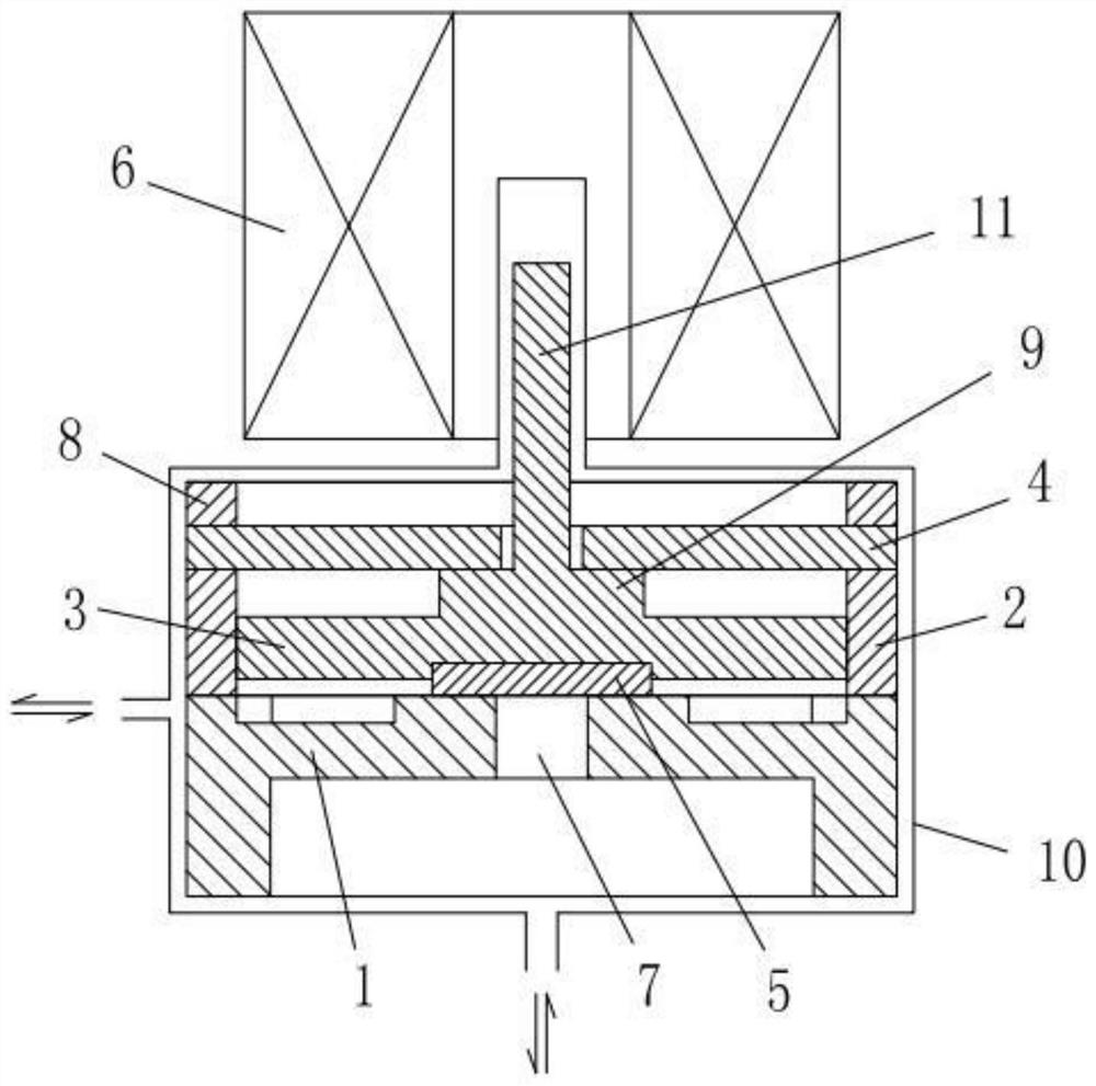
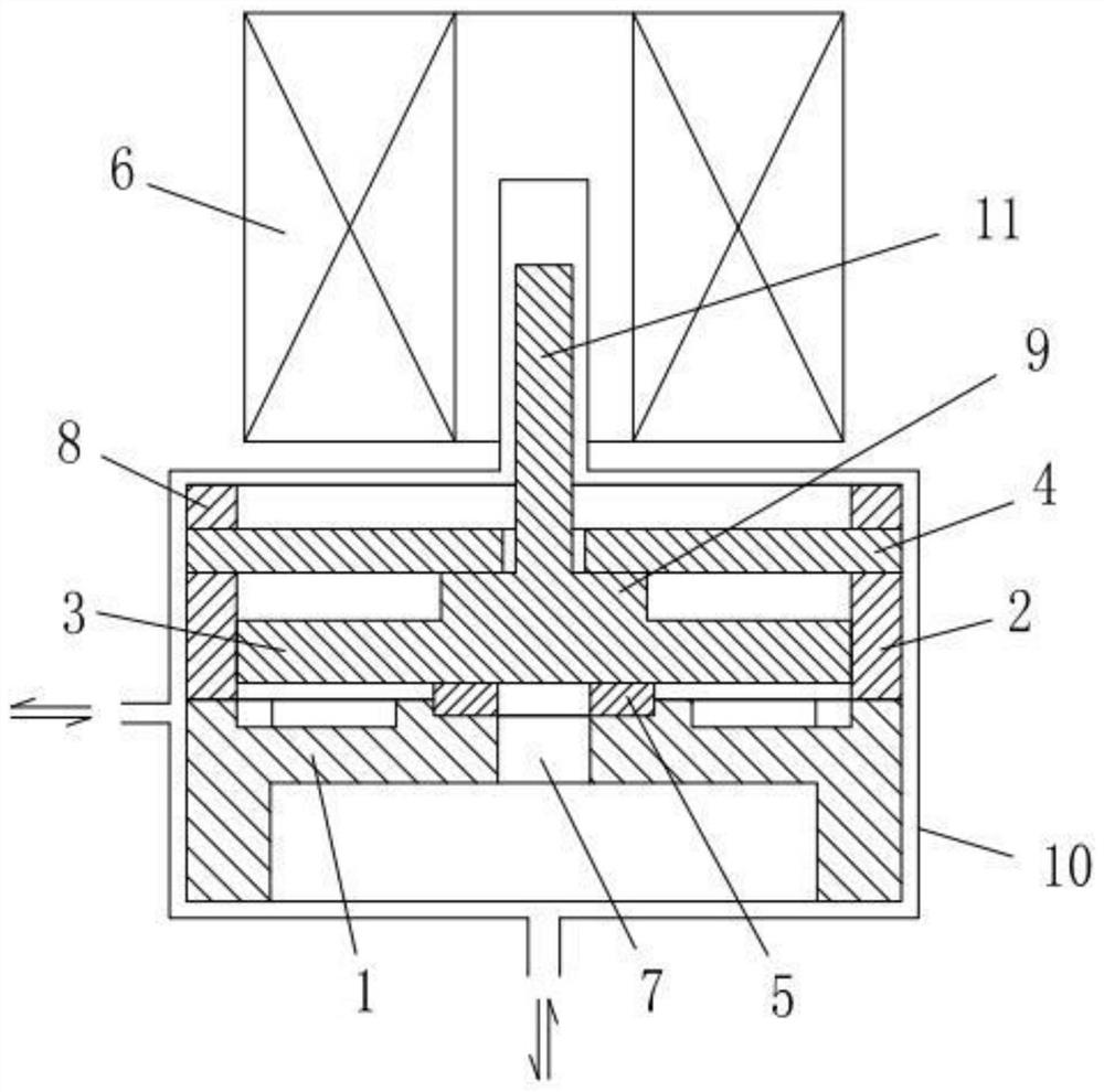
[0016] like Figure 1-2 As shown in the figure, a closed precision flow control mechanism according to the present invention includes a closed space 10 and an electromagnetic coil 6. The closed space 10 can be a shell structure made of materials such as plastic or metal. The closed space 10 is provided with a base 1, Ring base 2 , floating part 3 , elastic sheet 4 , gasket 5 and backing ring 8 .

[0017] The center of the base 1 is provided with a flow channel hole 7, the outer circumference of the upper side of the base 1 is provided with a plurality of arc-shaped baffle walls, the upper surfaces of the multiple arc-shaped baffle walls are flush, and the ring seat 2 is located on the outer circumference of the base 1. On the arc-shaped baffle walls, a fluid circulation opening structure is formed between adjacent arc-shaped baffle walls;


PUM


Abstract

The invention discloses a closed precise flow control mechanism which comprises a closed space and an electromagnetic coil, and a base, a ring seat, a floating component, an elastic piece and a gasket are arranged in the closed space; a runner hole is formed in the base, the ring seat is arranged on the base, the floating component is arranged in the ring seat, and the elastic piece is arranged on the upper side of the floating component. The electromagnetic coil is arranged on the outer side of the upper portion of the closed space, the closed space is provided with an upward protruding part, the floating component is provided with an electromagnetic induction part, and the electromagnetic induction part enters the protruding part of the closed space; according to the scheme, the mechanical structure part of the valve body is closed and isolated from the electromagnetic coil, so that special gas such as oxygen or hydrogen can pass through the valve; the electromagnetic induction part enters a space in the middle of the electromagnetic coil, so that the electromagnetic coil can drive the floating part to be opened and closed slightly through the electromagnetic induction part to control the flow of a flowing medium; the overall structure is simple, machining is convenient, the control precision can be improved, and cost is reduced.

Description


Claims


Application Information

Patent Timeline
Owner SUZHOU RAYONTECH TECH CO LTD
Why Eureka
Try Eureka