Automatic amplitude control for voltage controlled oscillator

Active Publication Date: 2011-12-15
ADVANCED MICRO DEVICES INC
View PDF2 Cites 15 Cited by
  • Summary
  • Abstract
  • Description
  • Claims
  • Application Information

AI Technical Summary

Benefits of technology

A method and circuit for calibrating a VCO is disclosed. In one embodiment, a circuit includes a VCO and a bias control circuit coupled to a tail node of the VCO. An amplitude control unit may also be coupled to the tail node, wherein the amplitude control unit is configured to determine the amplitude of a VCO output signal based on a voltage present on the t

Problems solved by technology

However, the amplitude cannot be excessive as the large amplitude swing will otherwise c

Method used


Image

  • Automatic amplitude control for voltage controlled oscillator
  • Automatic amplitude control for voltage controlled oscillator
  • Automatic amplitude control for voltage controlled oscillator

Examples


Embodiment Construction

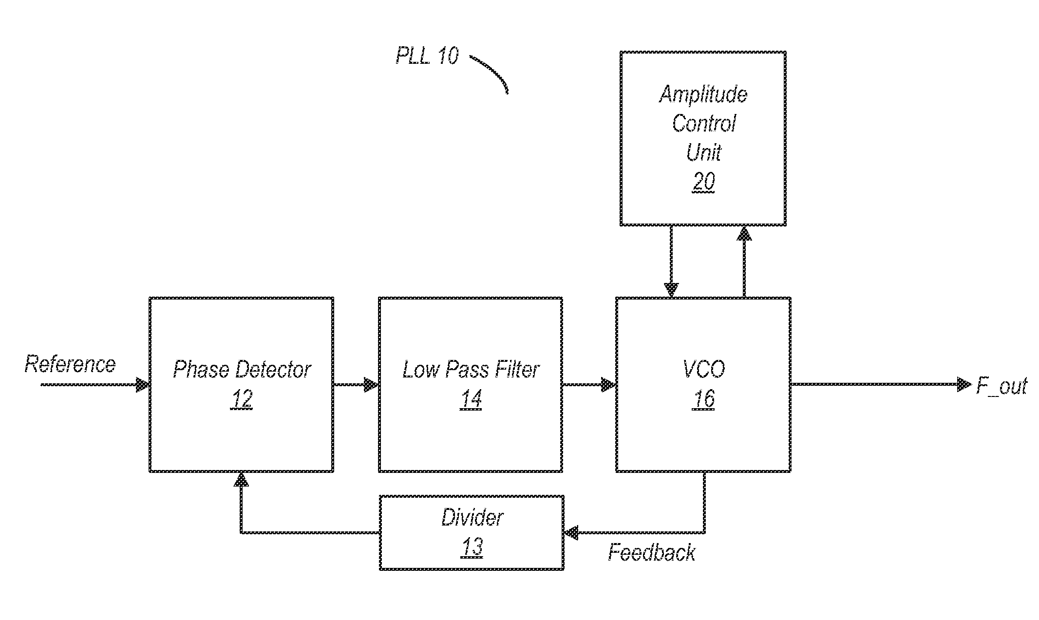
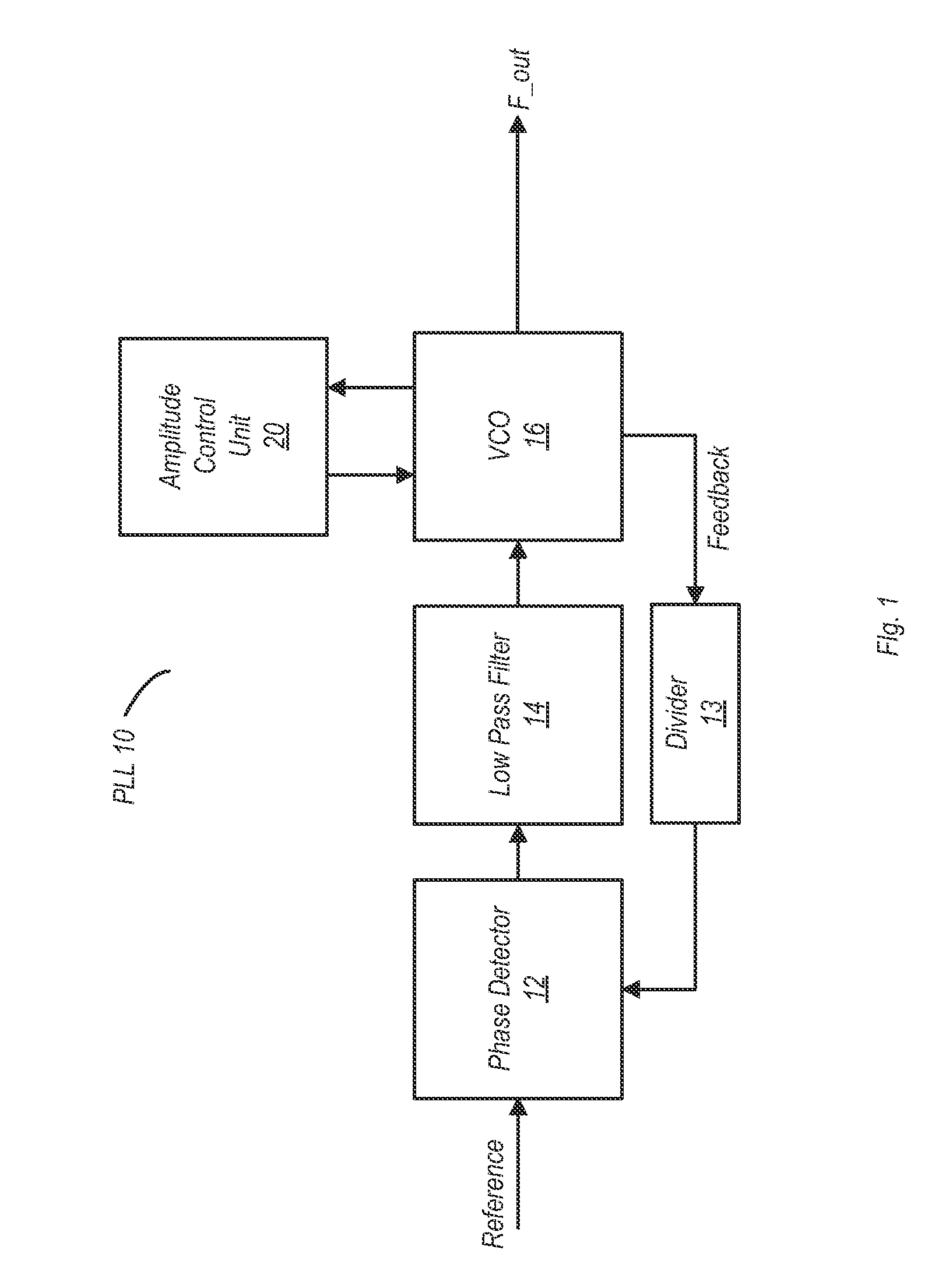
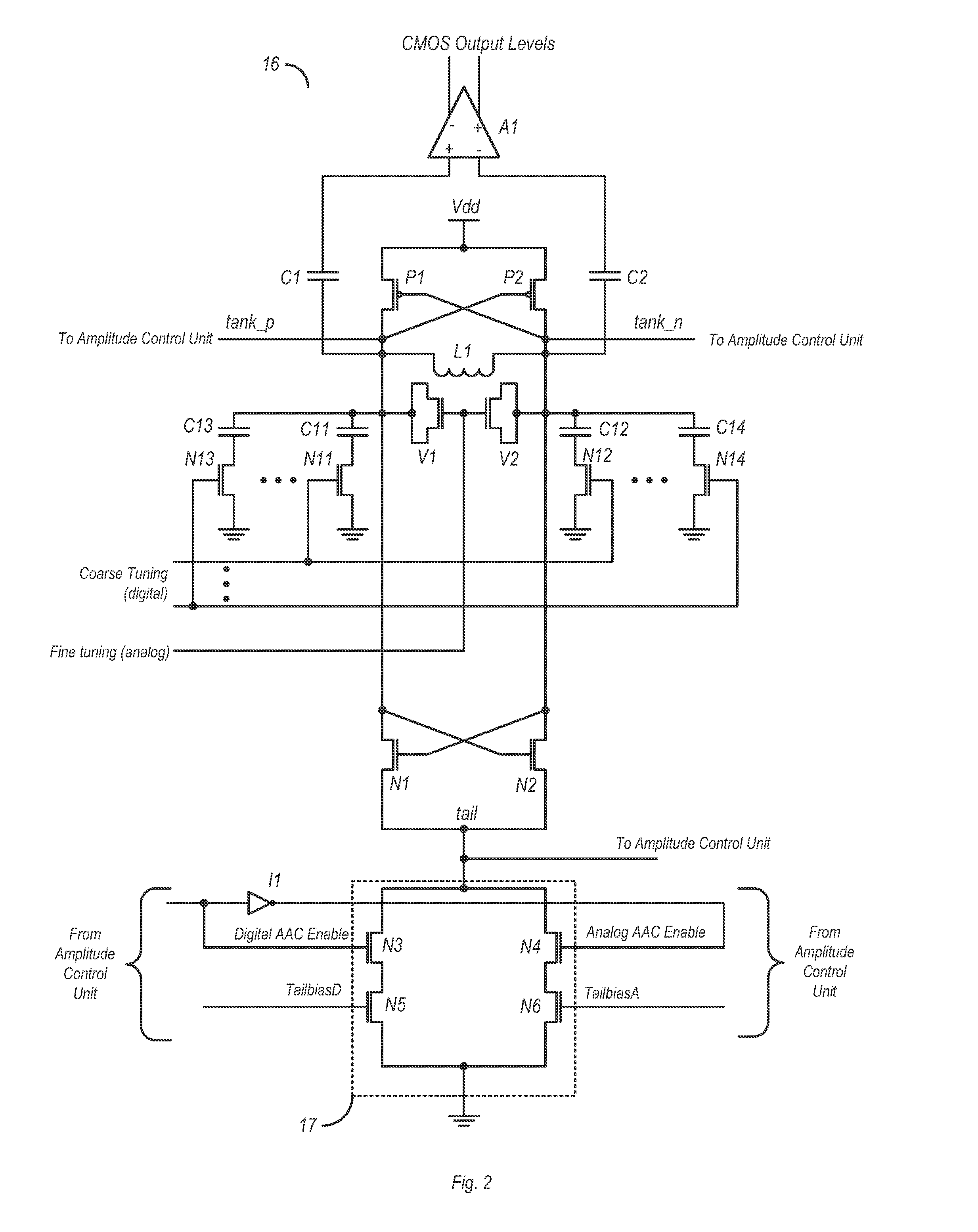
A method and apparatus for calibrating the amplitude of an output signal of a voltage-controlled oscillator (VCO) is described below by way of the examples in the drawings. The VCO may include an LC (inductive-capacitive) tank circuit. Monitoring of the output signal may be performed non-invasively by monitoring a tail node of the VCO instead of through a direct coupling to the LC tank circuit. By non-invasively monitoring the amplitude of the VCO output signal, problems such as loading (which can reduce the turning range of the LC tank circuit) may be avoided.

An amplitude control unit configured to calibrate the amplitude of the VCO output signal may determine its amplitude based on the voltage present on the tail node. Based on the tail node voltage and a target voltage, the amplitude control unit may determine whether or not the amplitude of the VCO output signal is within a specified range (e.g., if the tail node voltage exceeds the target voltage). If the amplitude is not within t


PUM


Abstract

A circuit and method for calibrating a VCO (voltage controlled oscillator) is disclosed. In one embodiment, a circuit includes a VCO and a bias control circuit coupled to a tail node of the VCO. An amplitude control unit may also be coupled to the tail node, wherein the amplitude control unit is configured to determine the amplitude of a VCO output signal based on a voltage present on the tail node. The amplitude control unit may also be configured to generate a bias voltage based on the amplitude of the VCO output signal and a target voltage. The bias control circuit may be coupled to receive the bias voltage from the amplitude control unit and may be further configured to adjust the voltage on the tail node based on the received bias voltage.

Description


Claims


Application Information

Patent Timeline
Owner ADVANCED MICRO DEVICES INC
Why Eureka
Try Eureka