Reproduction apparatus and reproduction method
- Summary
- Abstract
- Description
- Claims
- Application Information
AI Technical Summary
Benefits of technology
Problems solved by technology
Method used
Image

Examples
embodiment 1
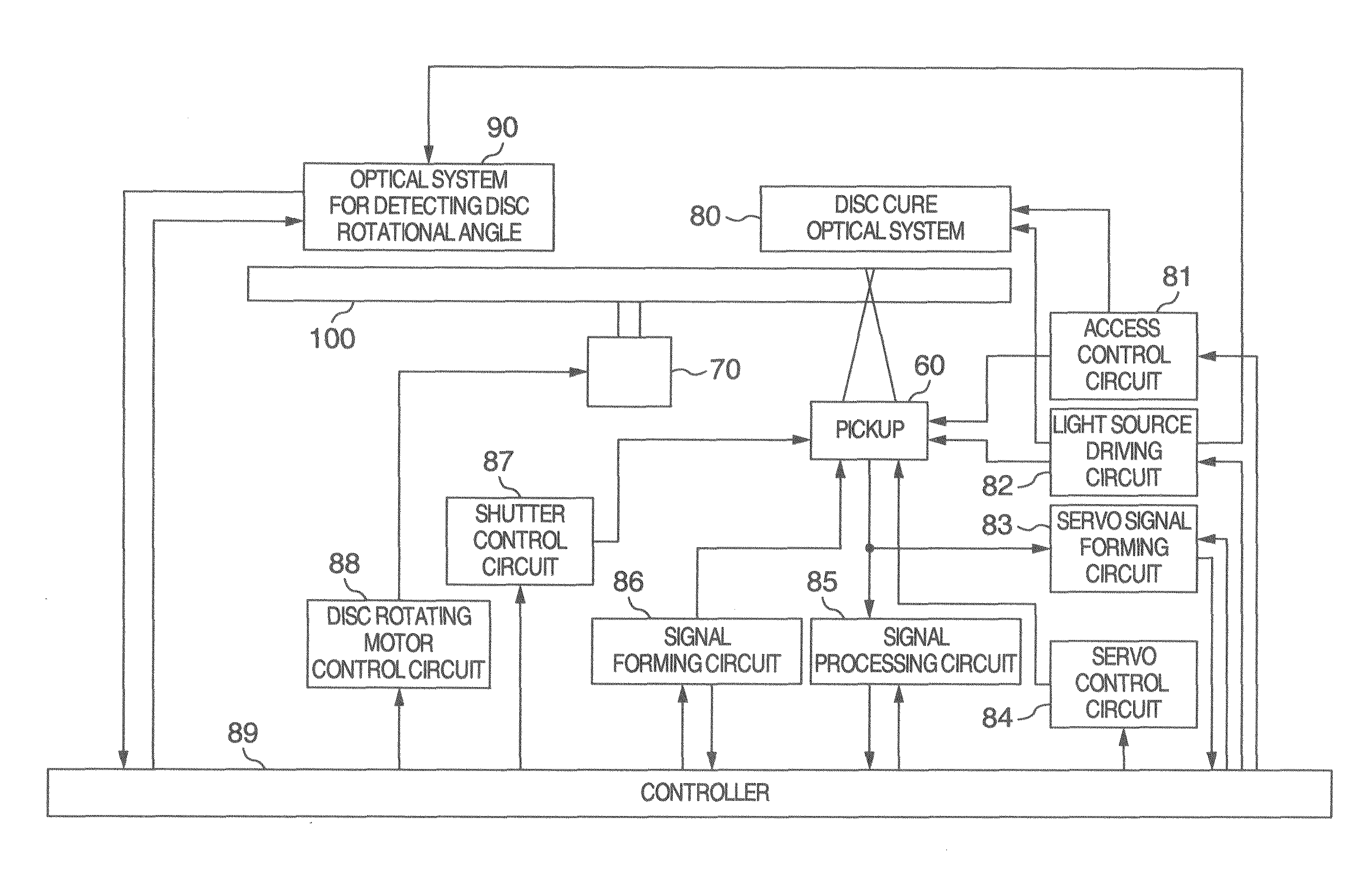
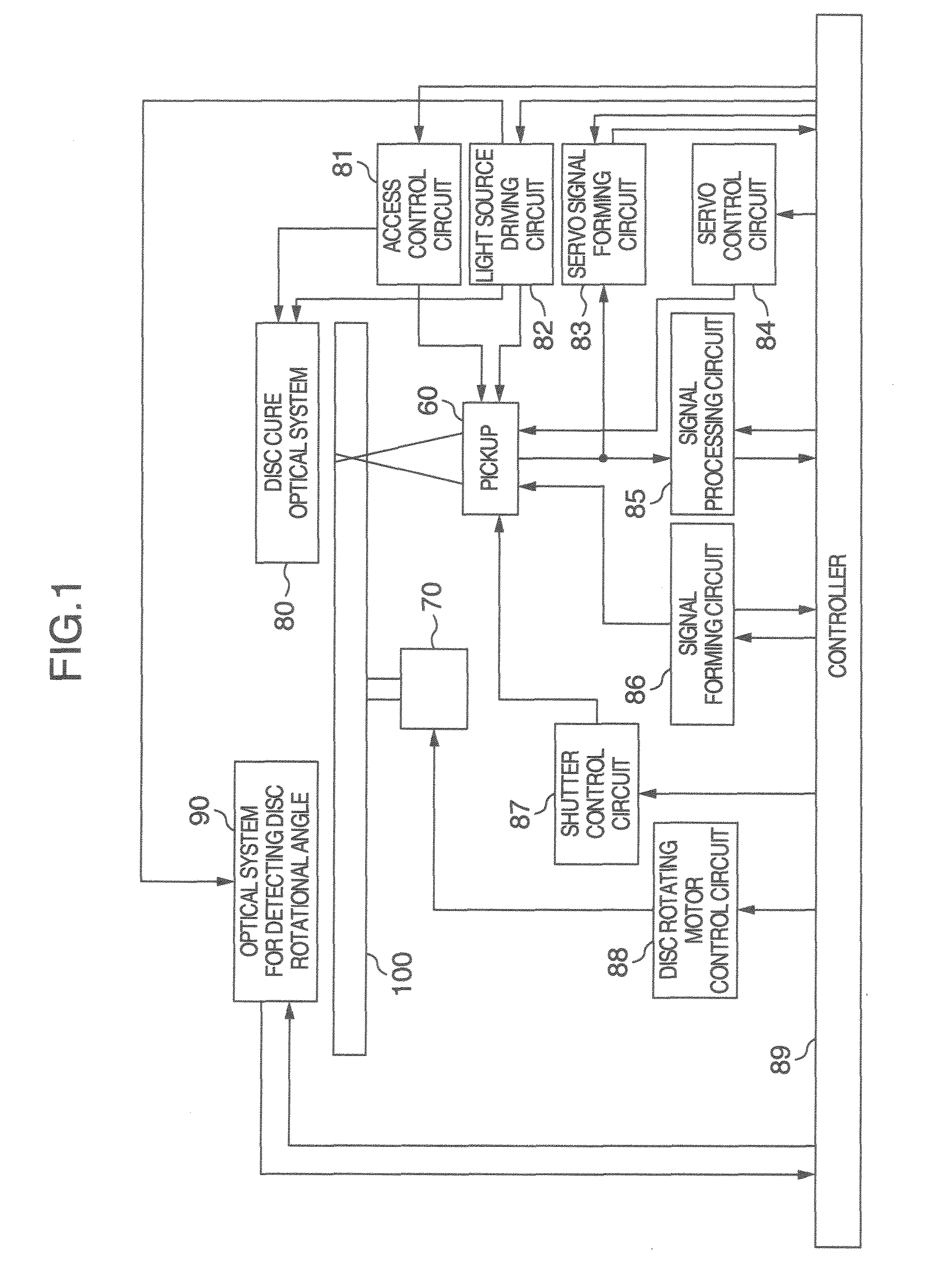
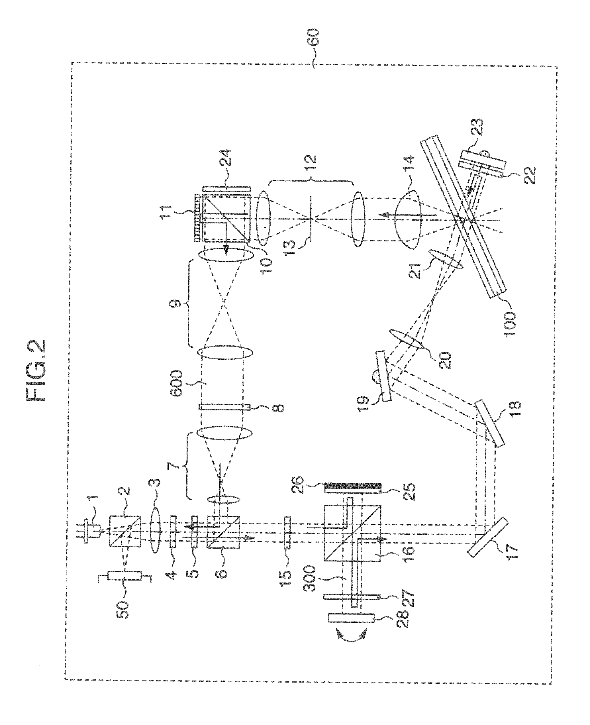
[0025]First, an example of a whole configuration of an apparatus in the embodiment will be described. FIG. 1 shows a whole configuration of a holographic memory apparatus for recording and / or reproducing digital information by using holography. The holographic memory apparatus has: an optical pickup device 60 having a configuration as illustrated in FIG. 2; a disc cure optical system 80; an optical system 90 for detecting a disc rotational angle; and a rotating motor 70. A hologram recording medium 100 can be rotated by the rotating motor 70.
[0026]The optical pickup device 60 plays a role for emitting reference light and signal light to the hologram recording medium 100 and recording digital information by using the holography.
[0027]At this time, an information signal to be recorded is sent to a space light modulator in the optical pickup device 60 by a controller 89 through a signal forming circuit 86. The signal light is modulated by the space light modulator.
[0028]In the case of r
embodiment 2
[0055]In the holographic memory apparatus in the embodiment, for example, in the case of reproducing the page data in order from the first page, the second page, . . . , the ith page, the (i+1)th page, . . . , the timing when the incident angle at which the light amount of the diffracted light 600 becomes the peak is detected by using the output value of the photodetector 50 may be detected during the reproduction of the page data of the ith page in order to previously obtain the incident angle of the reference light 200 for reproducing the page data of the (i+1)th page. Details will be described hereinbelow with reference to FIG. 6.
[0056]As mentioned above, the reference light 200 and control light 300 whose polarizing directions cross perpendicularly enter the hologram recording medium 100. The incident angle of the reference light 200 has been preset to the incident angle adapted to reproduce the page data of the ith page. The page data of the ith page is reproduced by the image pic
PUM
 Abstract
Description
Claims
Application Information
 - R&D Engineer
- R&D Manager
- IP Professional
- Industry Leading Data Capabilities
- Powerful AI technology
- Patent DNA Extraction
Browse by: Latest US Patents, China's latest patents, Technical Efficacy Thesaurus, Application Domain, Technology Topic.
© 2024 PatSnap. All rights reserved.Legal|Privacy policy|Modern Slavery Act Transparency Statement|Sitemap