High temperature thermal energy storage system

a technology of thermal energy storage and high temperature, which is applied in the direction of indirect heat exchangers, machines/engines, light and heating equipment, etc., can solve the problems of fracture and gravelization of the pcm

Inactive Publication Date: 2012-03-08
FEHER PETER
View PDF13 Cites 88 Cited by
  • Summary
  • Abstract
  • Description
  • Claims
  • Application Information

AI Technical Summary

Benefits of technology

This patented technology allows for better control over how heated up an object's temperature can affect it. It uses a special type of substance called PCM, which changes from solid state when they absorb energy. When charged by melting them down, it becomes more viscous and forms a tightly packaged structure. These structures are designed to allow for easy movement within the body while still maintaining their effectiveness.

Problems solved by technology

The technical problem addressed in this patent is that conventional high temperature thermal storage systems involve complicated and expensive equipment and materials, which can lead to decreases in performance and increase costs. Additionally, existing methods like encasing the entire system into balls or cylinders may result in reduced thermal conduction and efficiency.

Method used


Image

  • High temperature thermal energy storage system
  • High temperature thermal energy storage system
  • High temperature thermal energy storage system

Examples


Embodiment Construction

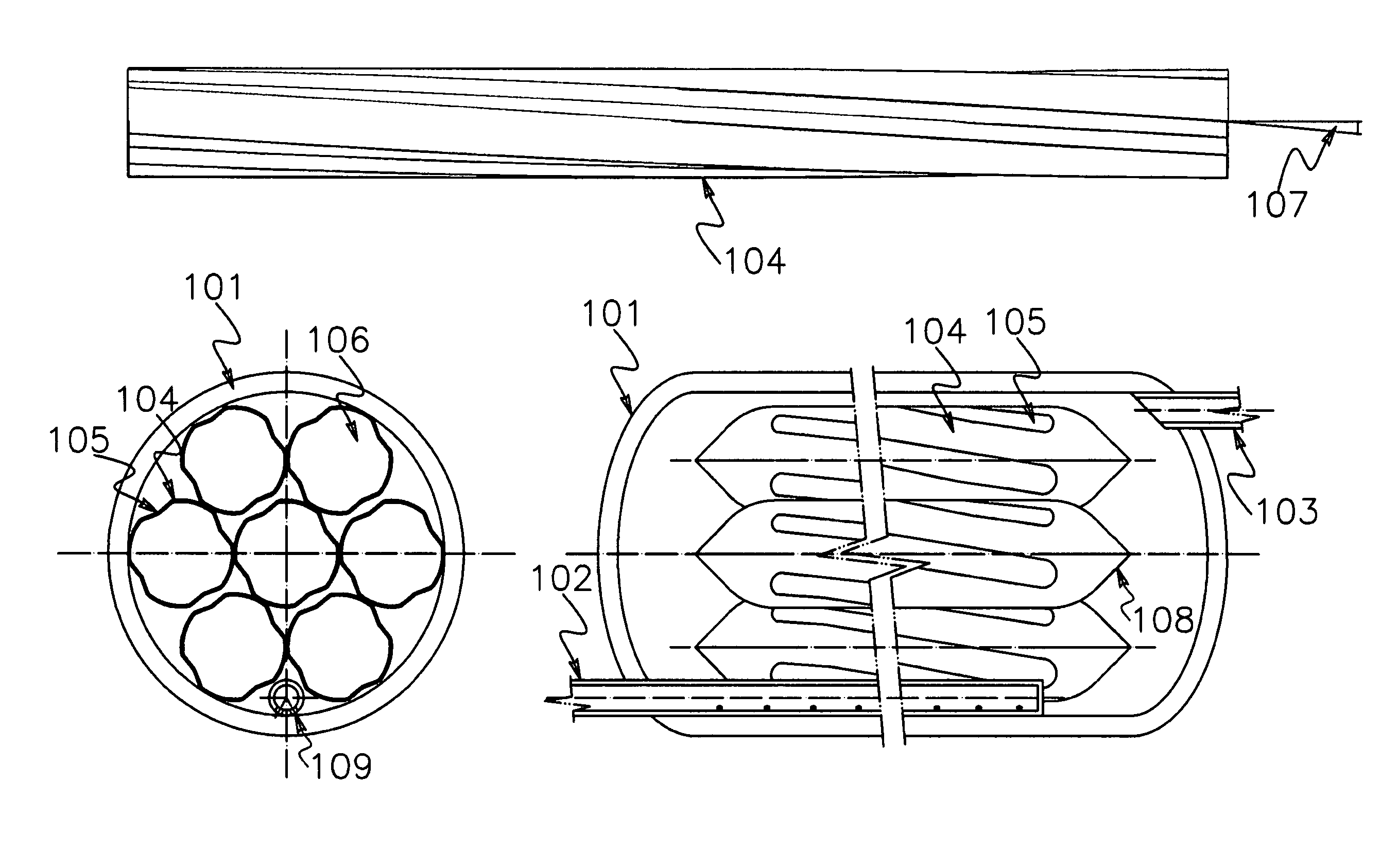
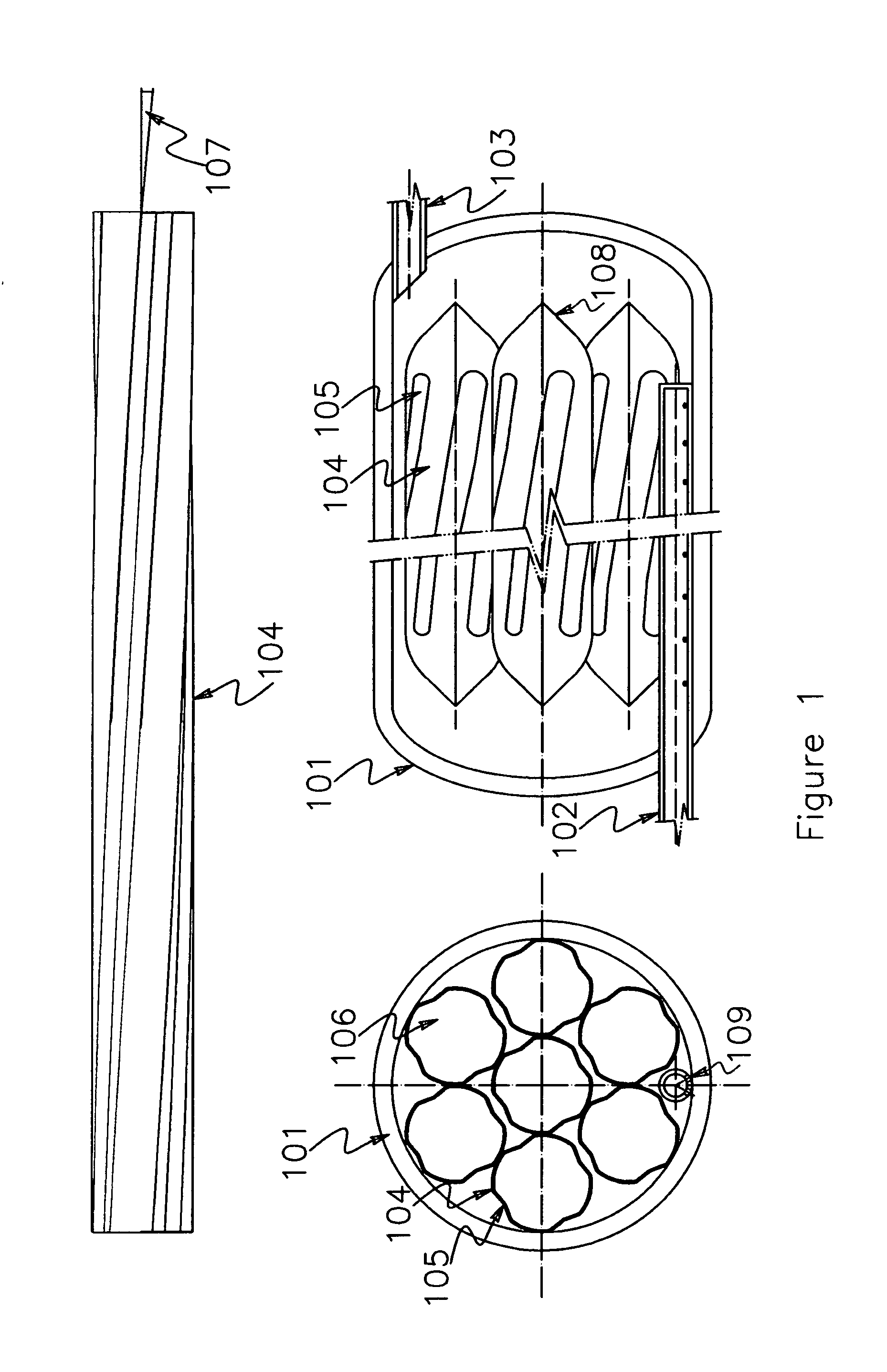
[0018]Referring now to the drawings, in which like numerals indicate like elements throughout the several views, FIG. 1 depicts one embodiment of the helically grooved tube-capsules 104. The capsules may be formed from a thin wall metal tube by enrolling helical grooves along the length of the tubes or by extrusion or other metal forming procedure. The grooved tubes may resemble the rifled barrel of guns. The ratio of the length to the diameter of the tube is from 6 to 300. The angle 107 between the tangent of the helix of the grooves and the axis of the tube may be from 0 to 30 degrees. The shape of the profile of the groove 105 is curved that may be circular or oval. The number of the grooves on the tube may be from 2 to 12. The ratio of the depth of the groove to the diameter of the tube may be from 0.02 to 0.4. The purpose of the grooving is to provide radial and axial flexibility of the tube wall to accommodate the thermal expansion of the encapsulated phase change material. At th


PUM


Abstract

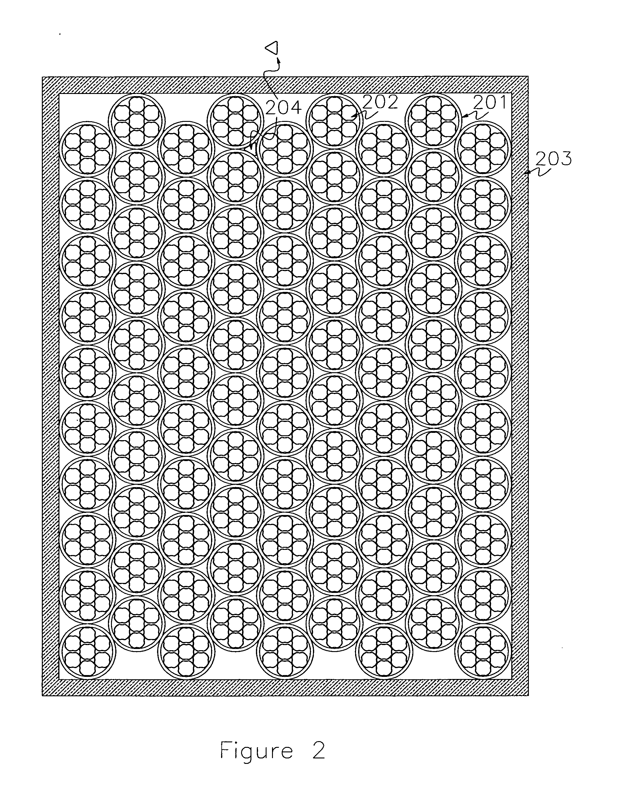
High temperature thermal energy storage system comprised of solid-liquid phase change material that is fully encapsulated in helically grooved, sealed, thin-wall, metal tubes. Multitude of horizontally oriented, pressure-rated steam pipes or vessels filled with PCM tube capsules form a battery of thermal storage system. The steam pipes in the battery are connected through a common liquid-side distribution header system and a common steam-side distribution header system. Multitude of steam pipes stacked up to fill a block-shaped container space. This insulated enclosure provides the basis for simple fabrication, transport and filed-erection and forms the basic building block for a modular thermal storage system.

Description


Claims


Application Information

Patent Timeline
Owner FEHER PETER
Why Eureka
Try Eureka