Thermal management of environmentally-sealed electronics enclosure

Inactive Publication Date: 2012-05-31
TELECOMM SYST INC
View PDF32 Cites 9 Cited by
  • Summary
  • Abstract
  • Description
  • Claims
  • Application Information

AI Technical Summary

Problems solved by technology

Existing cooling techniques within an environmentally-sealed enclosure implement active forced air cooling; passive convec

Method used


Image

  • Thermal management of environmentally-sealed electronics enclosure
  • Thermal management of environmentally-sealed electronics enclosure
  • Thermal management of environmentally-sealed electronics enclosure

Examples


Embodiment Construction

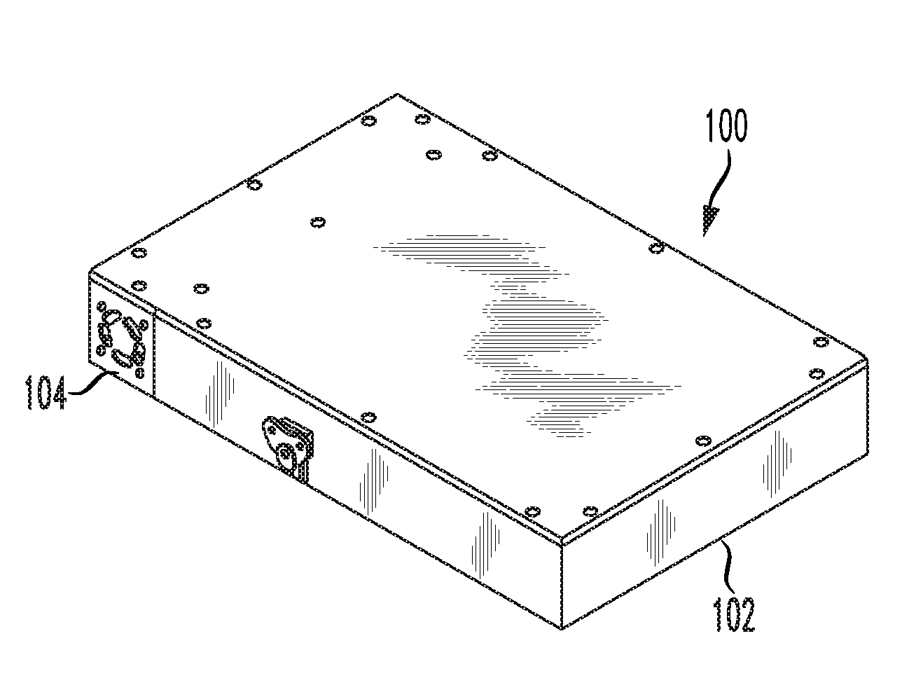
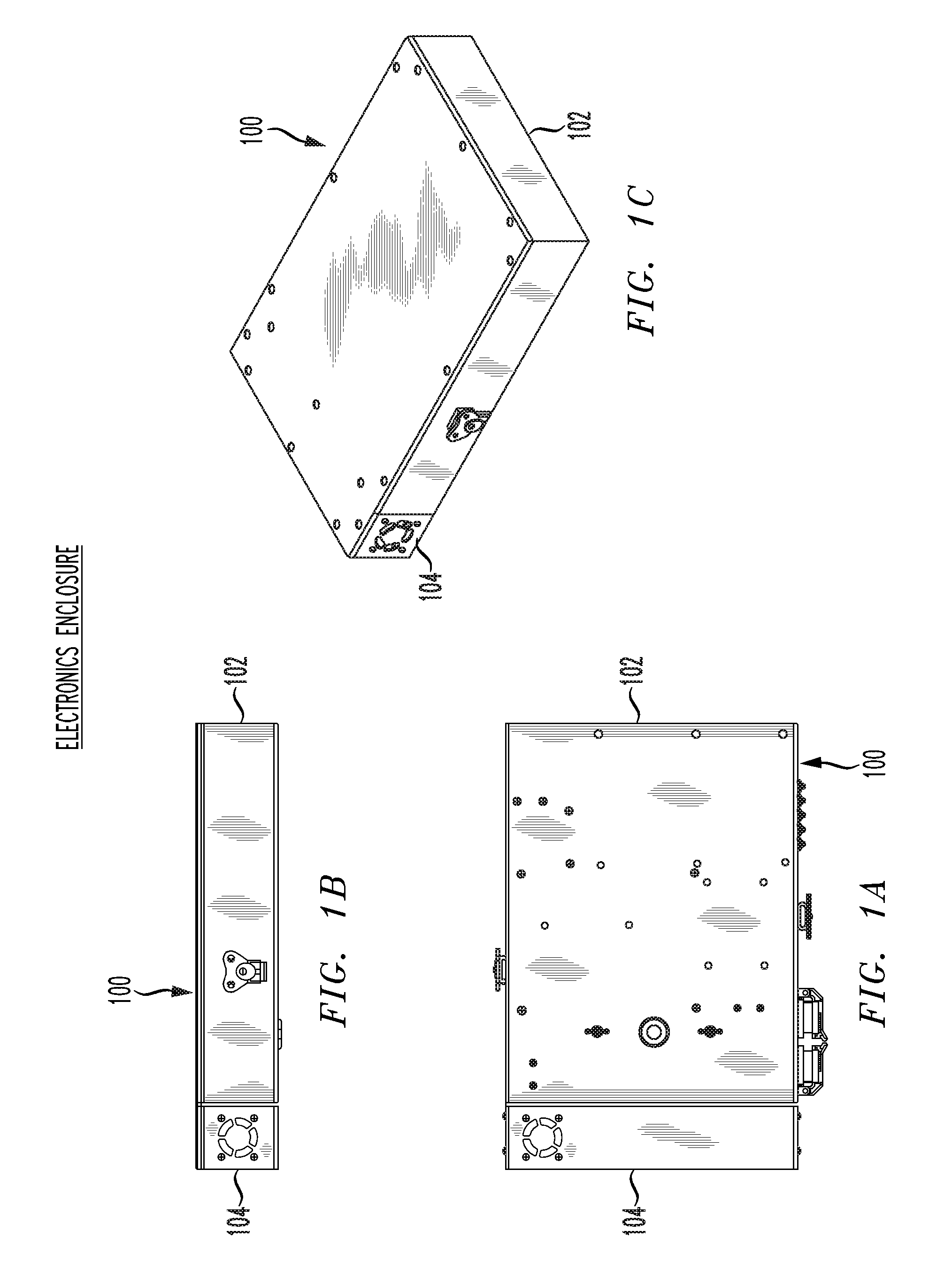
[0013]The present invention provides successful and efficient extraction and removal of excessive heat that is generated by operating electronic components within an environmentally-sealed enclosure, thus maintaining a sufficiently cool internal environment to allow housed electronic devices to operate within their respective acceptable operational temperature limits. The invention accomplishes efficient extraction and removal of excessive heat without direct transmission of a viscous medium (air, coolant, etc.) through the environmentally-sealed enclosure, thereby allowing for the operation of the electronics enclosure in harsh environments including dust, sand, precipitation, fog, corrosive salt air, etc.

[0014]A thermal management system is disclosed whereby a combination of conductive and convective heat transfer schemas are employed to eliminate and discard excessive heat from within an environmentally-sealed electronics enclosure to its ambient surroundings.

[0015]FIGS. 1A to 1C sh


PUM


Abstract

Heat generated by operating electronic components within an environmentally-sealed enclosure is removed, without direct transmission of a viscous medium through the enclosure. An internal heat sink and external heat sink each span a given wall. The internal heat sink section is baffled and channeled with one place for air to enter, and one to exit. A fan forces air over heat sink extremities of the internal heat sink section. A circulating air column entrapped within the enclosure is drawn into the entrance of the internal heat sink, and forced through the entire length of the internal heat sink, providing for a thermal conduit for a heated entrapped air column to transfer its heat into the internal heat sink. The external heat sink is exposed to the ambient environment, with airflow managed over the external heat sink preferably with a structural surround that provides for channeling of airflow.

Description


Claims


Application Information

Patent Timeline
Owner TELECOMM SYST INC
Why Eureka
Try Eureka