Power supply apparatus for test apparatus

a technology of power supply apparatus and test apparatus, which is applied in the direction of pulse manipulation, pulse technique, instruments, etc., can solve the problems of affecting the accuracy of the approximation, and affecting the quality of the approximation

Active Publication Date: 2012-08-30
ADVANTEST CORP
View PDF6 Cites 6 Cited by
  • Summary
  • Abstract
  • Description
  • Claims
  • Application Information

AI Technical Summary

Benefits of technology

The invention helps optimize the performance of electronic devices by controlling their electrical properties based on its own resistance. This means that it can work better with other components without affecting them or causing damage.

Problems solved by technology

The technical problem addressed in this patent is how to improve the performance of a power supply apparatus used for testing electronic devices without sacrificing their quality or functionality.

Method used


Image

  • Power supply apparatus for test apparatus
  • Power supply apparatus for test apparatus
  • Power supply apparatus for test apparatus

Examples


Embodiment Construction

[0030]The invention will now be described based on preferred embodiments which do not intend to limit the scope of the present invention but exemplify the invention. All of the features and the combinations thereof described in the embodiment are not necessarily essential to the invention.

[0031]In the present specification, the state represented by the phrase “the member A is connected to the member B” includes a state in which the member A is indirectly connected to the member B via another member that does not substantially affect the electric connection therebetween, or that does not damage the functions or effects of the connection therebetween, in addition to a state in which the member A is physically and directly connected to the member B.

[0032]Similarly, the state represented by the phrase “the member C is provided between the member A and the member B” includes a state in which the member A is indirectly connected to the member C, or the member B is indirectly connected to the


PUM


Abstract

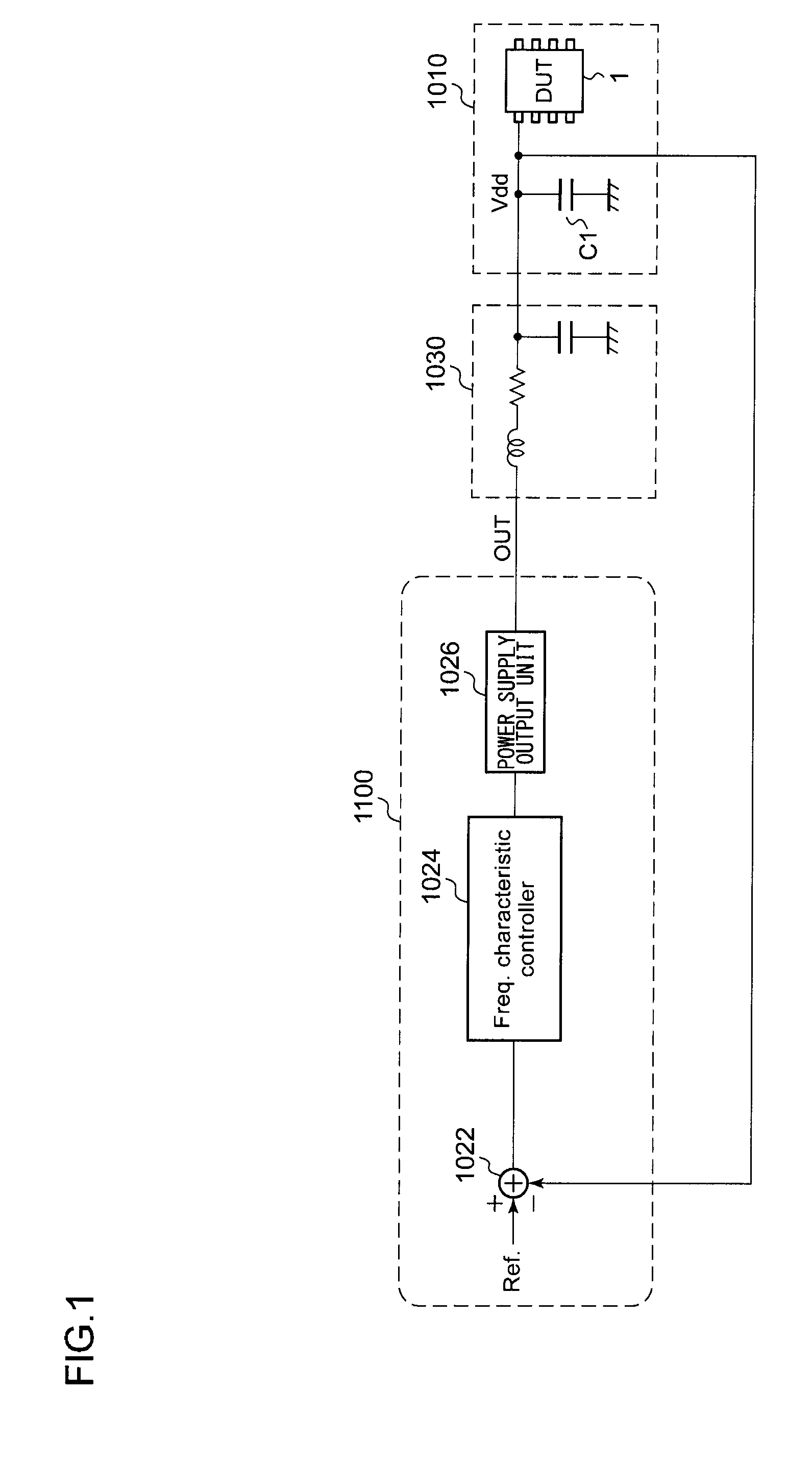
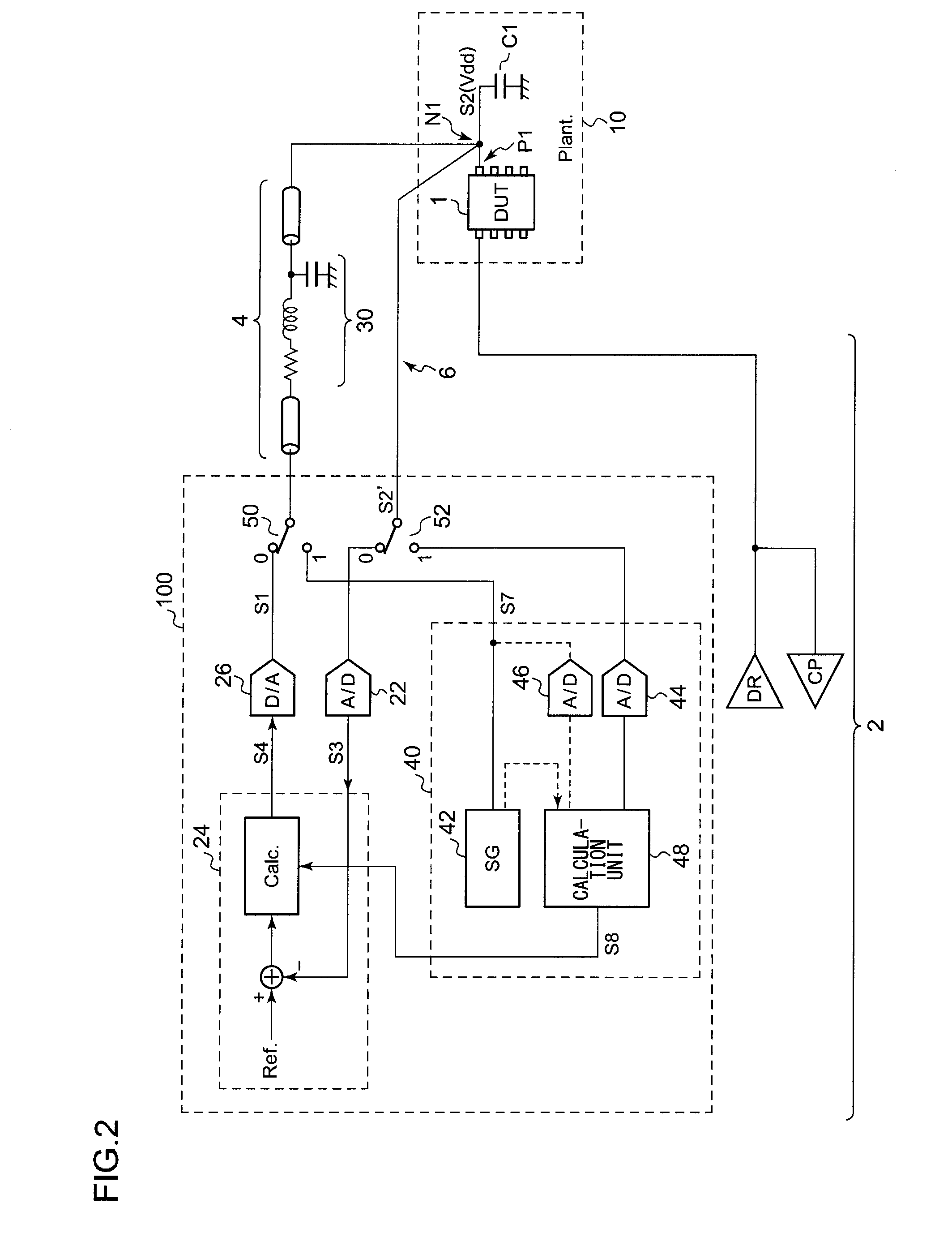
A first A/D converter converts an analog observed value, which corresponds to a power supply signal supplied to a power supply terminal of a DUT, into a digital observed value. By means of digital calculation processing, a digital signal processing circuit generates a control value that is adjusted such that the digital observed value matches a predetermined reference value. A first D/A converter supplies, via a power supply line to the power supply terminal of the DUT, an analog power supply signal obtained by performing digital/analog conversion of the control value. A load estimating unit applies a test signal containing a predetermined frequency component via the power supply line to a node via which the power supply terminal is to be connected, and generates a control parameter for the digital signal processing circuit according to the test signal and the observed signal.

Description


Claims


Application Information

Patent Timeline
Owner ADVANTEST CORP
Why Eureka
Try Eureka