Connector assembly

Inactive Publication Date: 2012-12-13
CHENG UEI PRECISION IND CO LTD
View PDF10 Cites 2 Cited by
  • Summary
  • Abstract
  • Description
  • Claims
  • Application Information

AI Technical Summary

Benefits of technology

[0006]As described above, the connector assembly of the present invention utilizes flexible, watertight, light in weight and small in volume characteristics of the FPC board to meet the demands of watertight, small and light wrist watches. Furthermore, the one end of the FPC board together with the soldering tails of the terminals are embedded in the insulating body as an integral when the insulating body is molded, so that further strengthens the connection between the soldering tails and the FPC board.

Problems solved by technology

However, the USB cable is apt to fall off and even be fractured from the USB connector after the wrist watch is worn and taken off again and again, on account of a weak soldering between the USB cable and the USB connector and a weak flexibility of the USB cable.
But, it increases a whole thickness of the watchstrap of the wrist watch and results in a worse effect on comfortable wear of the wrist watch.

Method used


Image

  • Connector assembly
  • Connector assembly
  • Connector assembly

Examples


Example

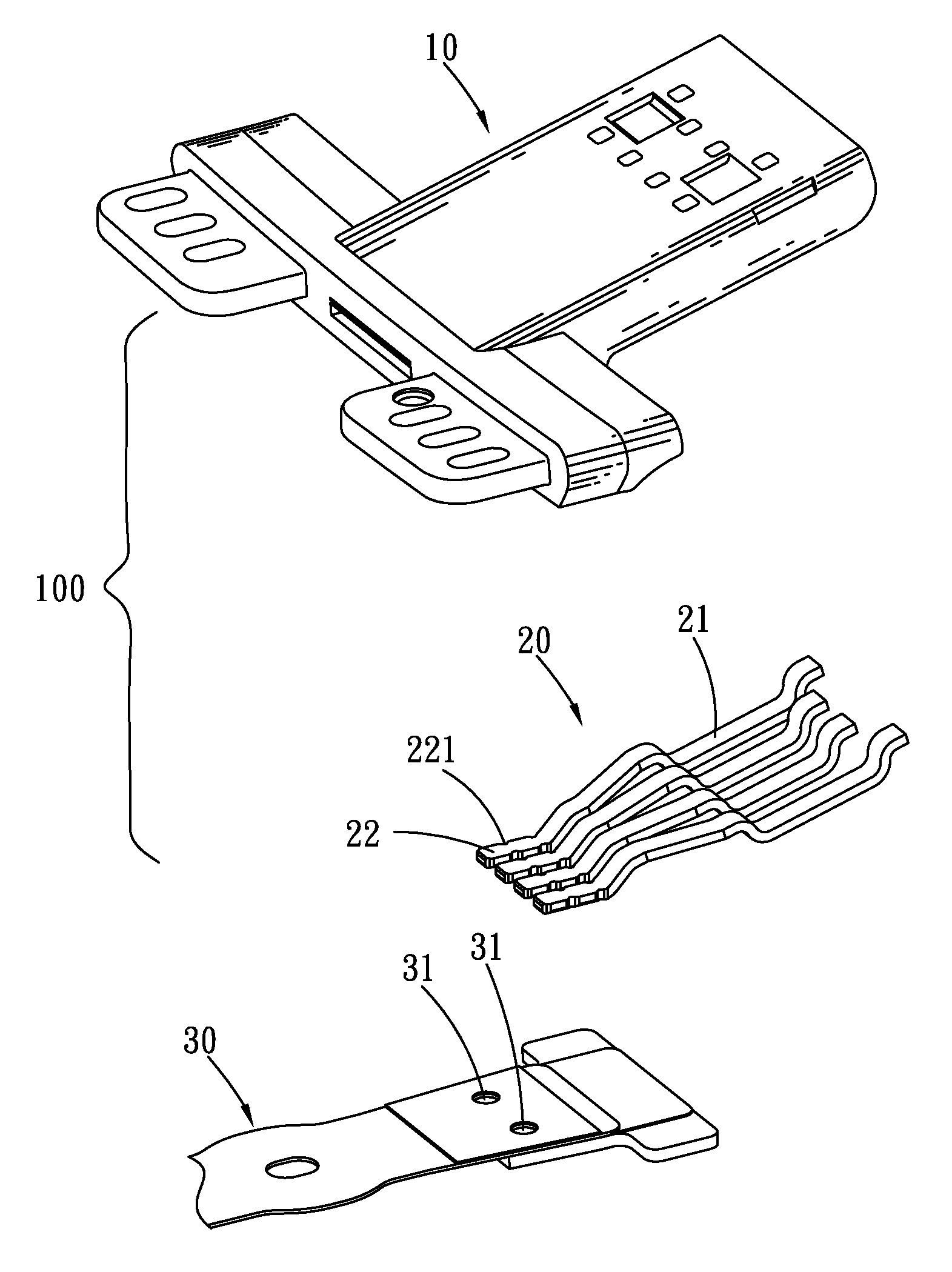
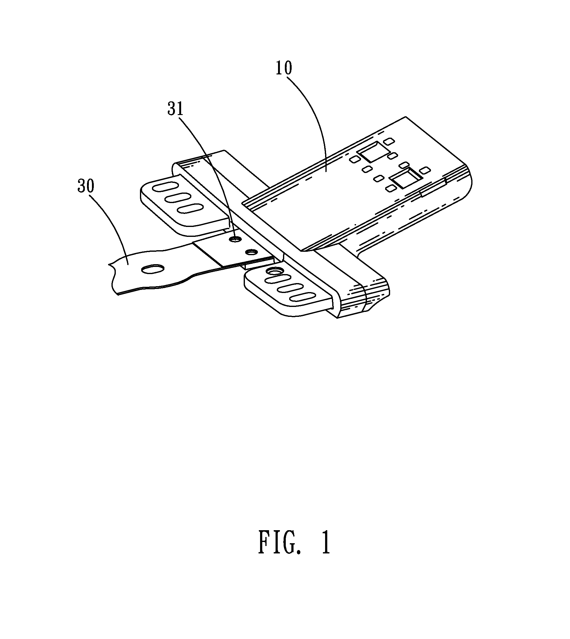
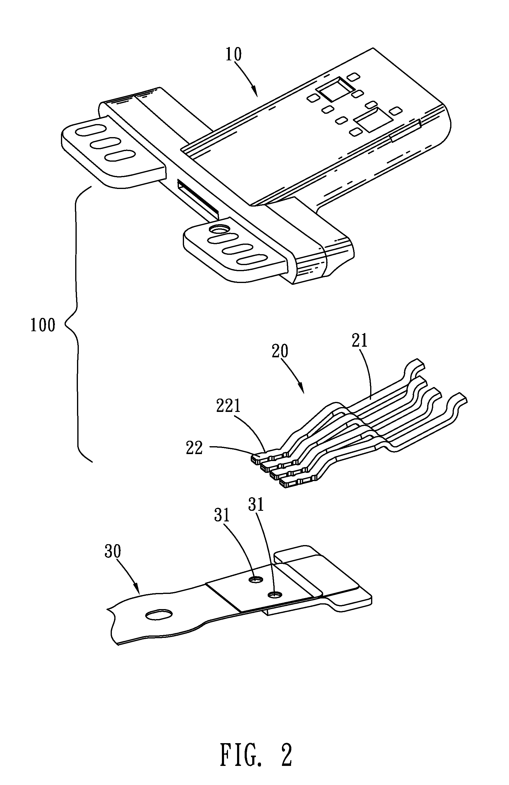
[0010]With reference to FIG. 1 and FIG. 2, a connector assembly according to an embodiment of the present invention includes a connector 100 and a FPC (Flexible Printed Circuit) board 30 electrically connected with the connector 100. The connector 100 includes an insulating body 10 and a plurality of terminals 20 soldered to one end of the FPC board 30 by means of solder press welding. Then the terminals 20 and the one end of the FPC board 30 soldered with the terminals 20 are together molded in the insulating body 10 once in a single mold (not shown).

[0011]Referring to FIG. 2, each of the terminals 20 has a contact arm 21 and a soldering tail 22 of which two side edges define a plurality of gaps 221 capable of gathering melted solder therein so as to strengthen the weld between the terminal 20 and the FPC board 30. The one end of the FPC board 30 soldered with the terminals 20 defines a plurality of positioning holes 31 used to securely position the FPC board 30 together with the term


PUM


Abstract

A connector assembly adapted to be used in a wrist watch which has data transmission and storage functions, includes a connector including an insulating body and a plurality of terminals each having a soldering tail, and a FPC board acted as a watchstrap of the wrist watch or attached on an initial watchstrap of the wrist watch to electrically connect the connector and a circuit of the wrist watch. Wherein the soldering tails of the terminals are embedded in one end of the FPC board at regular intervals by means of solder press welding, then the one end of the FPC board together with the soldering tails of the terminals are molded in the insulating body as an integral, and the other end of the FPC board is electrically connected with the circuit of the wrist watch.

Description


Claims


Application Information

Patent Timeline
Owner CHENG UEI PRECISION IND CO LTD
Why Eureka
Try Eureka