Lever switch device

Active Publication Date: 2013-01-03
VALEO JAPAN CO LTD
View PDF3 Cites 2 Cited by
  • Summary
  • Abstract
  • Description
  • Claims
  • Application Information

AI Technical Summary

Benefits of technology

[0026]According to the invention, by adopting the means described above, the distal end portions where the first and second arms fit in the first and second

Problems solved by technology

This causes a problem that a width of the switch unit 105 in the lever axis direction is increased.
However, in case this configura

Method used


Image

  • Lever switch device
  • Lever switch device
  • Lever switch device

Examples


embodiment 1

Schematic Configuration

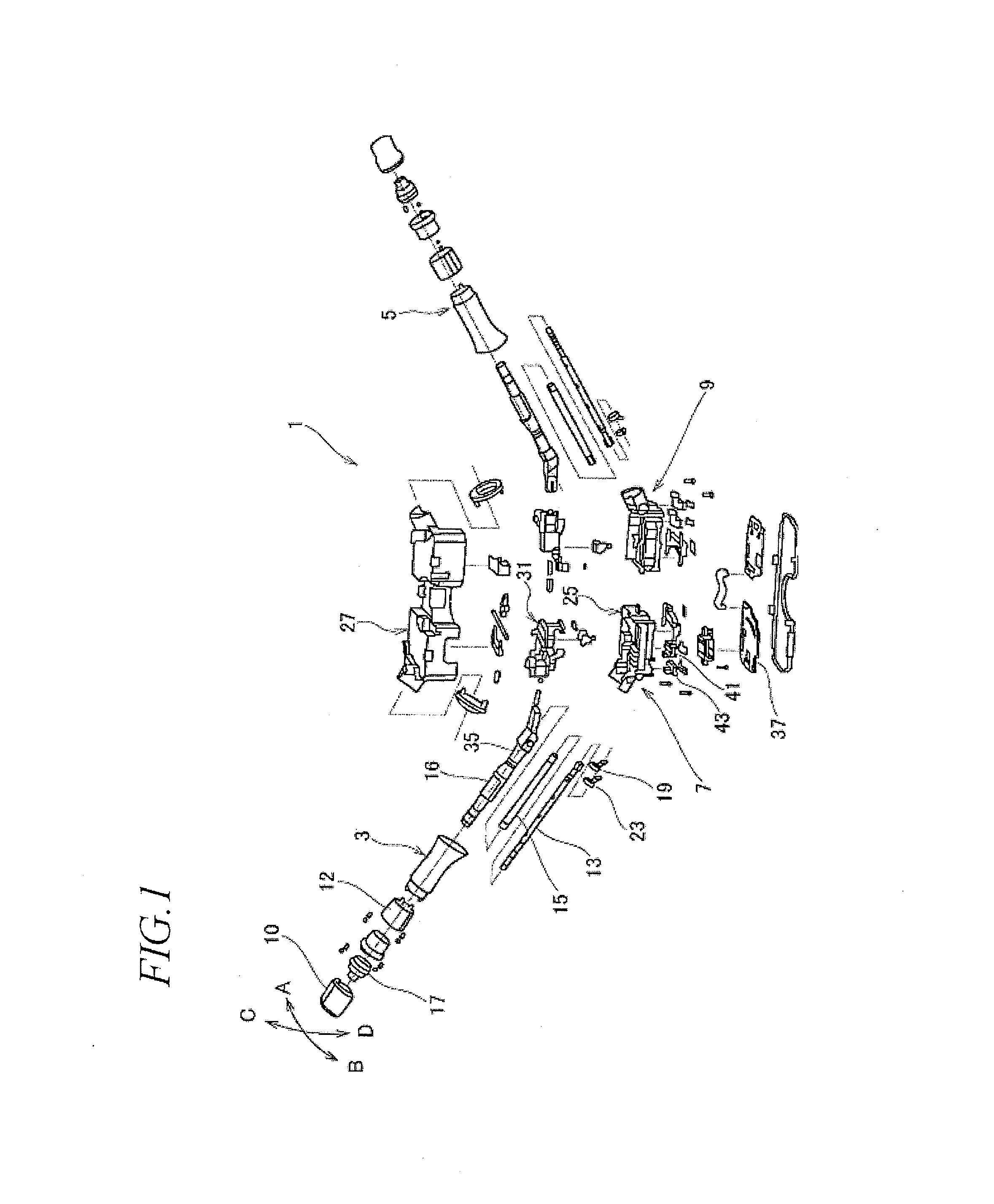
[0039]FIG. 1 is an overall exploded perspective view showing an assembling relation of a lever switch device to which Embodiment 1 of the invention is applied.

[0040]A lever switch device 1 shown in FIG. 1 is designed to issue electric controlling instructions and includes, for example, functions of a turn signal switch, a flash-to-pass switch, a main beam and dipped beam switching or dimmer switch and a headlamp switch.

[0041]The lever switch device 1 includes control levers 3, 5 and switch units 7, 9, and the switch units 7, 9 are mounted on a body side which is fixed to a steering column.

[0042]Here, the embodiment of the invention will be described by reference to the control lever 3 and the switch unit 7.

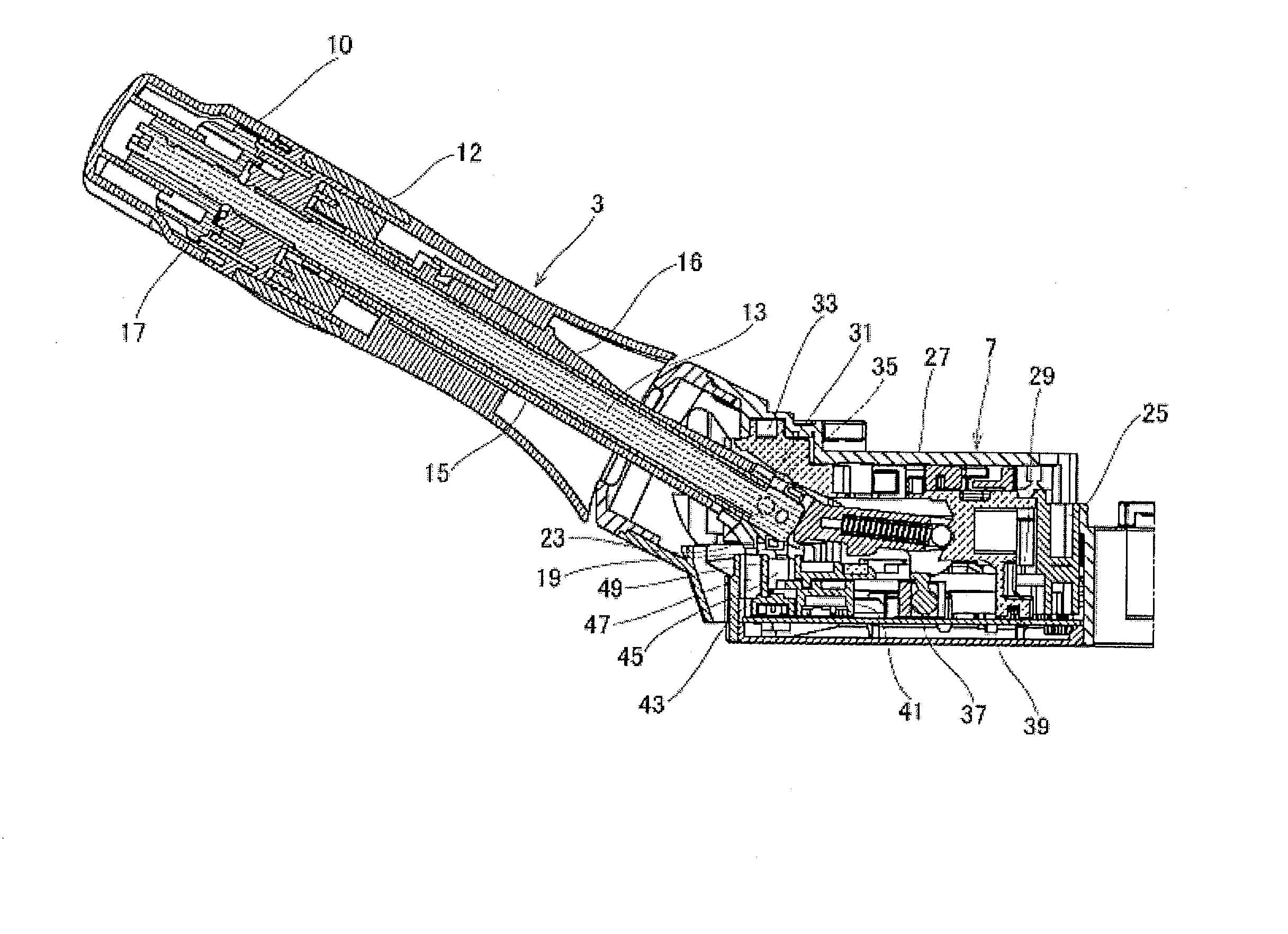
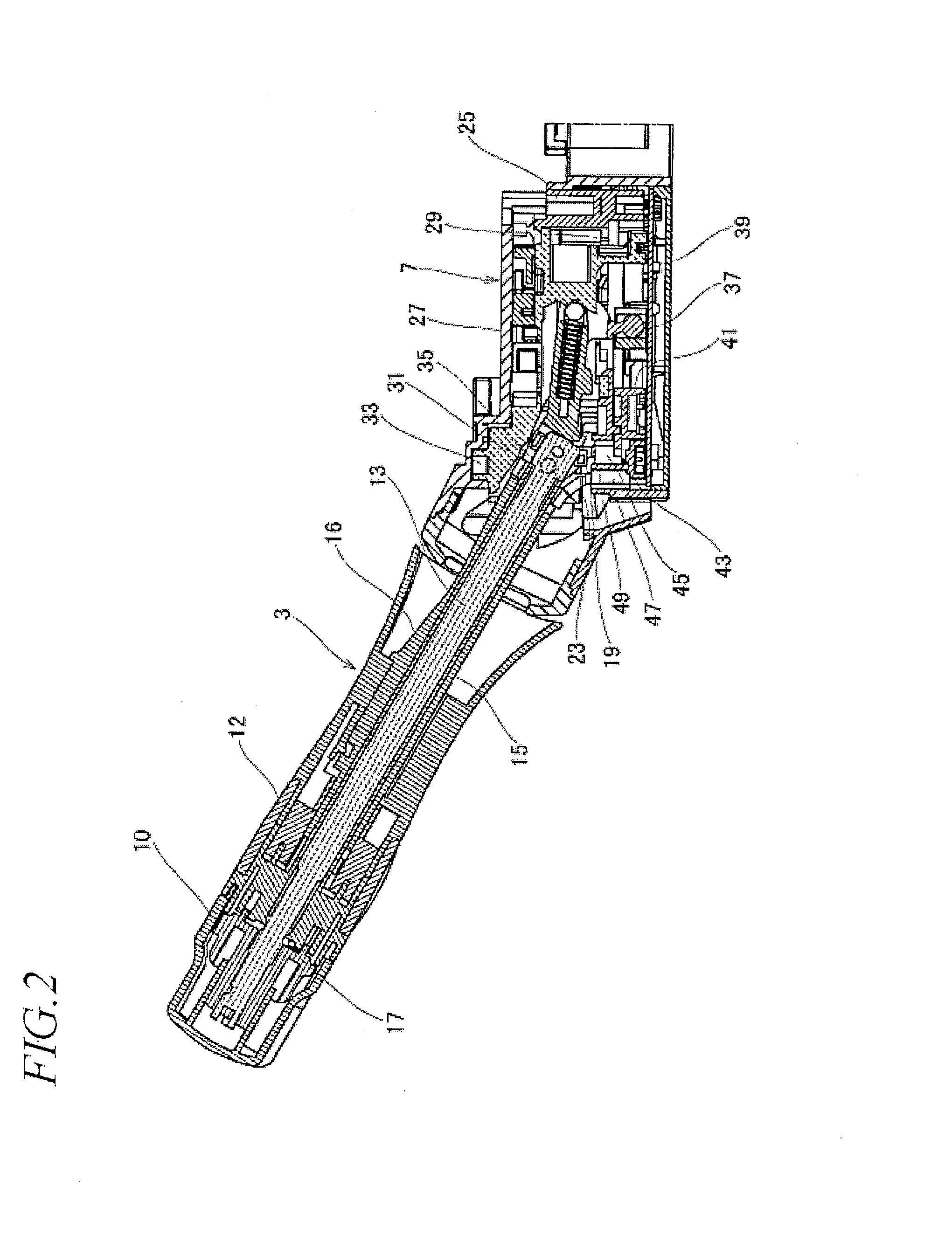
[0043]FIG. 2 is a sectional view of the control lever and the switch unit, and FIG. 3 is an enlarged sectional view of a main part.

[0044]As shown in FIG. 1, the control lever 3 swings freely in directions indicated by arrows A, B (directions following a steer


PUM


Abstract

The objective is to reduce the size of a lever switch device. Disclosed is a lever switch device provided with a restriction wall (49) which is formed between first and second arms (19, 23) and which restricts the movement of the first and second arms (19, 23) against the rotation of first and second levers (13, 15) relative to a movable body (31); and engagement walls (45a, 45b, 47a, 47b) which are formed on first and second fitting portions (45, 47) and which are engaged with the first and second arms (19, 23) by the rotational transfer of the first and second arms (19, 23) caused by the shaft rotation of the first and second levers (13, 15), to cause first and second movable boards (41, 43) to perform a contact operation.

Description


Claims


Application Information

Patent Timeline
Owner VALEO JAPAN CO LTD
Why Eureka
Try Eureka