Endoscopic Arrangement
a technology of endoscopy and arrangement, applied in the field of endoscopy arrangement, can solve the problems of increasing increasing the difficulty of cleaning, so as to reduce the manufacturing cost of the cable system, facilitate cleaning, and reduce the effect of manufacturing cos
- Summary
- Abstract
- Description
- Claims
- Application Information
AI Technical Summary
Benefits of technology
Problems solved by technology
Method used
Image

Examples
second embodiment
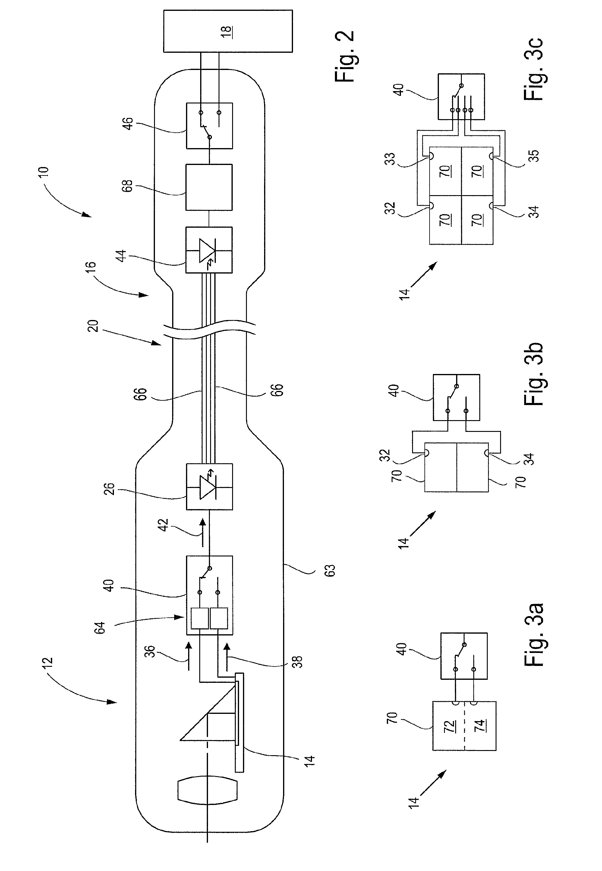
[0080]Different from FIG. 1 the endoscopic arrangement 10 is surrounded by a shell 63. The shell 63 protects the endoscopic arrangement from the outer environment, in particular from moisture.
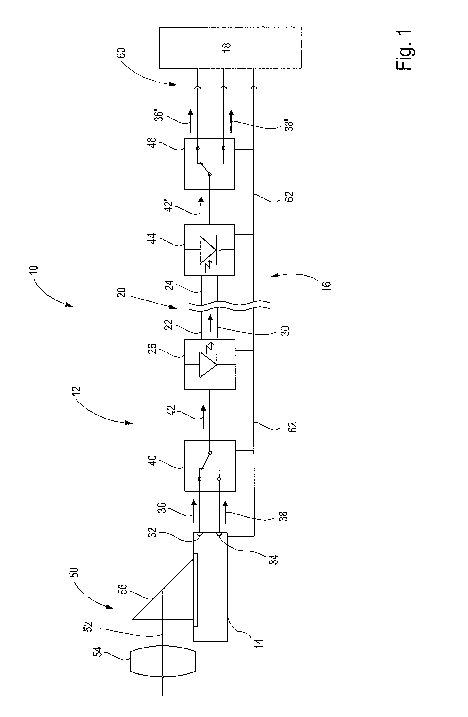
[0081]The first signal converter 40 comprises, in this embodiment, a buffer memory 64 to temporarily store at least one of the digital output signals 36, 38—here: both digital output signals 36, 38. This allows for a very flexible combination of the digital combined output signal 42.
[0082]The data transmission element 20 comprises, in this embodiment, at least two fibers 66. The signal converter 40 is configured to couple the digital combined output signal 42 into the two fibers 66 of the data transmission element 20. The coupling into the two fibers 66 can be achieved by a light source in the electro-optical converter 26 which couples light into both fibers 66 and which is preferably embodied as a laser diode. In order to achieve an additional safety it is preferable that the coupling into the t
first embodiment
[0084]FIG. 3a shows an imaging device 14. An image sensor 70 is shown with a continuous imaging area, wherein a first part 72 and a second part 74 of the imaging area are read out separately via the data outputs 32 and 34.
[0085]FIG. 3b shows a second embodiment of an imaging device 14. Here, two image sensors 70 are provided which are each read out via a data output 32 and 34, respectively.
third embodiment
[0086]FIG. 3c shows an imaging device 14. Here, four imaging sensors 70 are provided which are each read out via a data output 32, 33, 34, 35, respectively.
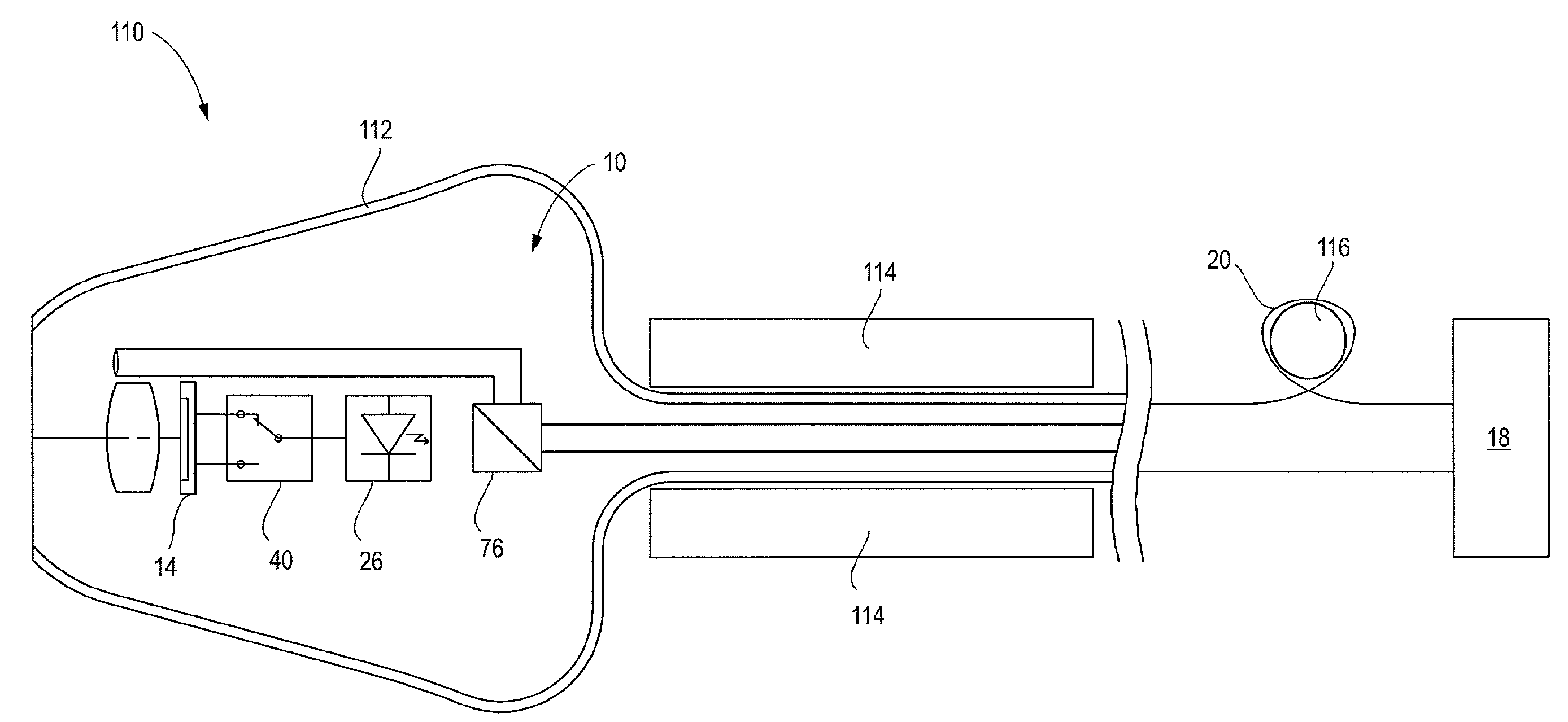
[0087]FIG. 4 shows a third embodiment of an endoscopic arrangement. Here, a spectral divider 76 is arranged between the electro-optical converter 26 and the second distal end 22 of the data transmission element 20. Further, at the first proximal end 24 of the endoscopic arrangement 10 a light source 78 is provided, here: integrated into the electrical unit 18, the light source 78 configured to couple light 80 at the first proximal end 24 into the data transmission element 20. The coupling is achieved via a further spectral divider 82.
[0088]At the first distal end 12 of the endoscopic arrangement 10 there is provided an exit 84 for visible light and a luminescence converter 86, wherein the luminescence converter 86 is configured to change light that is guided in the data transmission element 20 into white light and guide it to the ex
PUM
 Abstract
Description
Claims
Application Information
 - R&D Engineer
- R&D Manager
- IP Professional
- Industry Leading Data Capabilities
- Powerful AI technology
- Patent DNA Extraction
Browse by: Latest US Patents, China's latest patents, Technical Efficacy Thesaurus, Application Domain, Technology Topic.
© 2024 PatSnap. All rights reserved.Legal|Privacy policy|Modern Slavery Act Transparency Statement|Sitemap