System and method for remote monitoring of equipment moisture exposure

Inactive Publication Date: 2013-03-14
SCAPIER BRUCE
View PDF23 Cites 10 Cited by
  • Summary
  • Abstract
  • Description
  • Claims
  • Application Information

AI Technical Summary

Benefits of technology

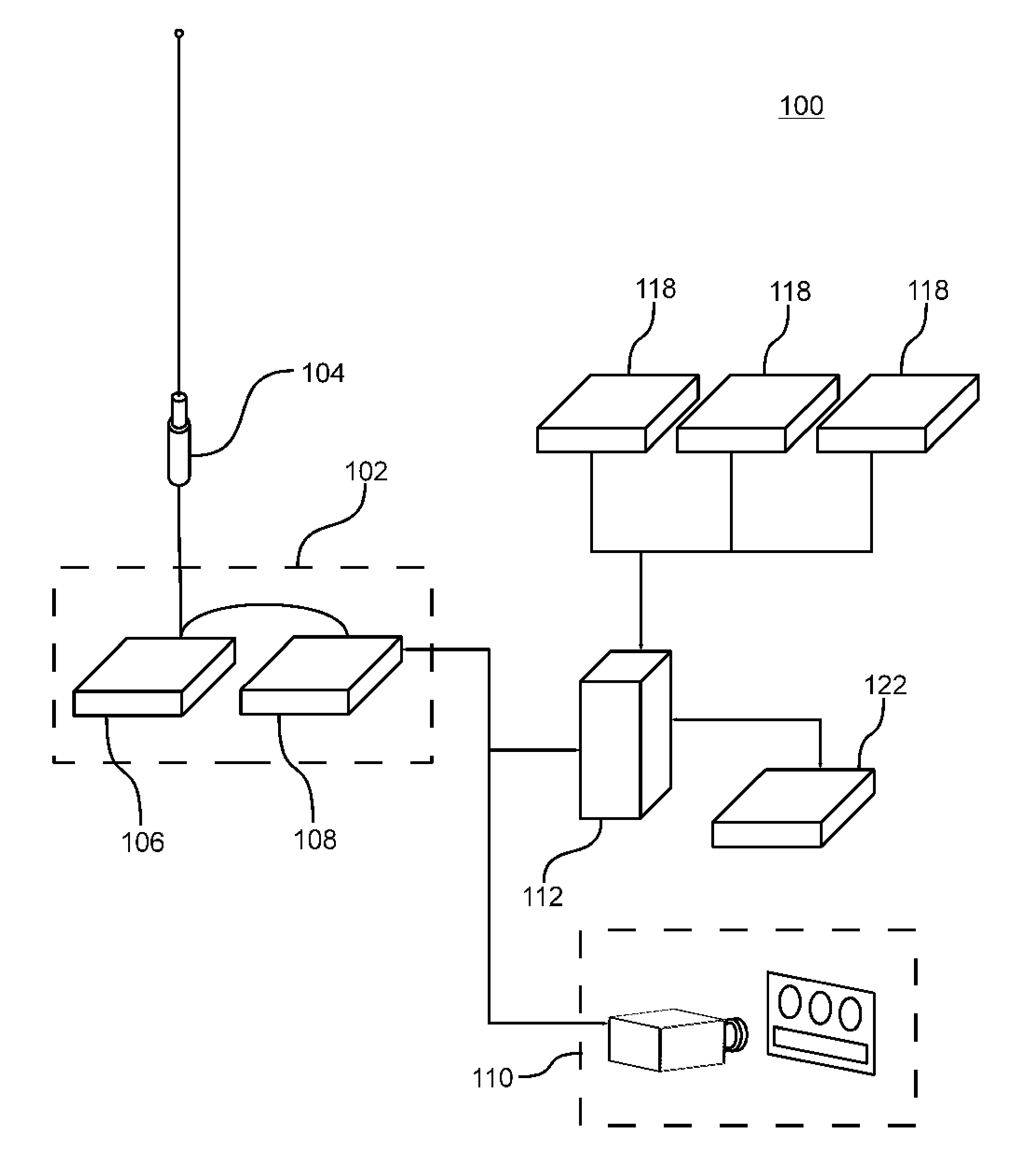
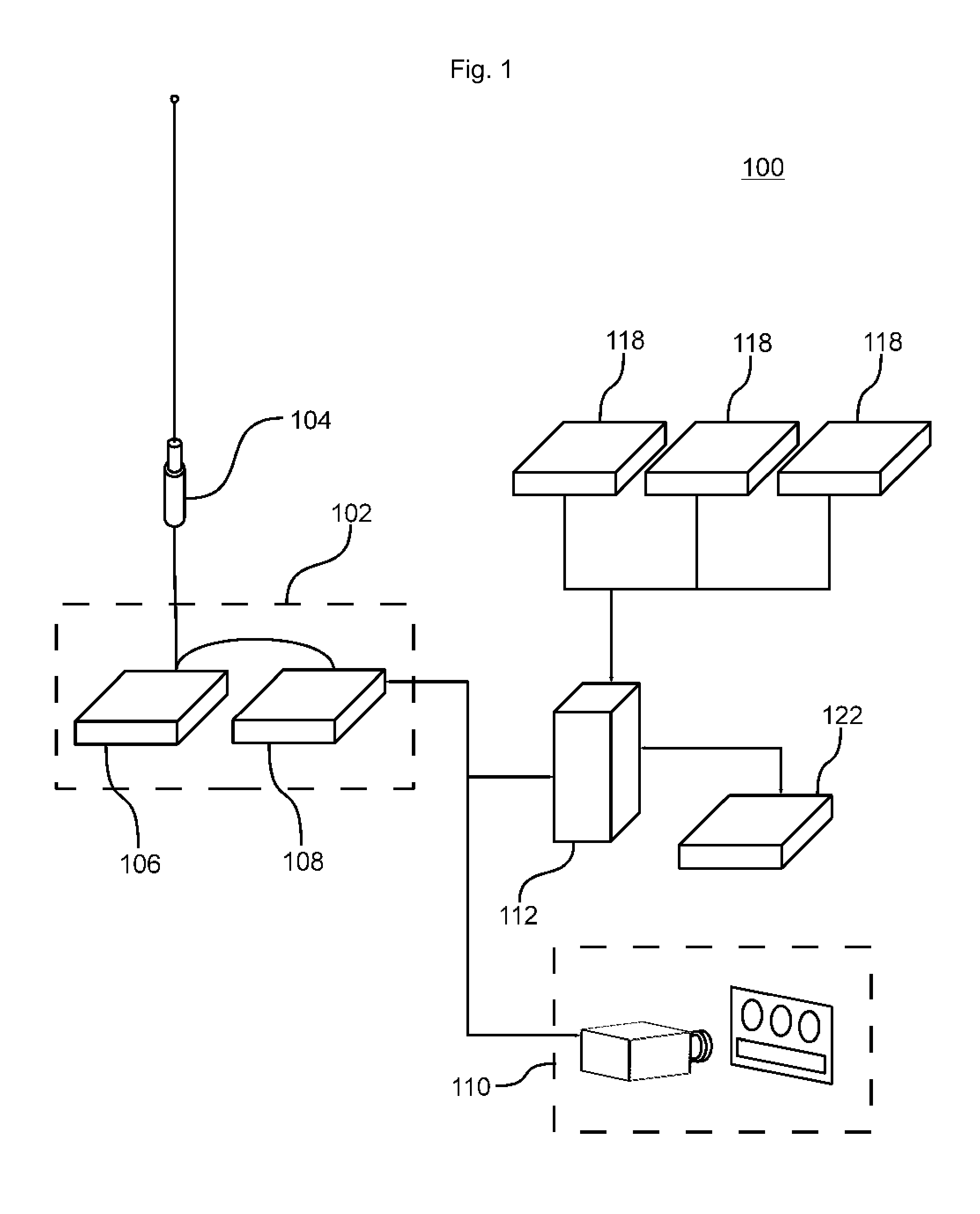
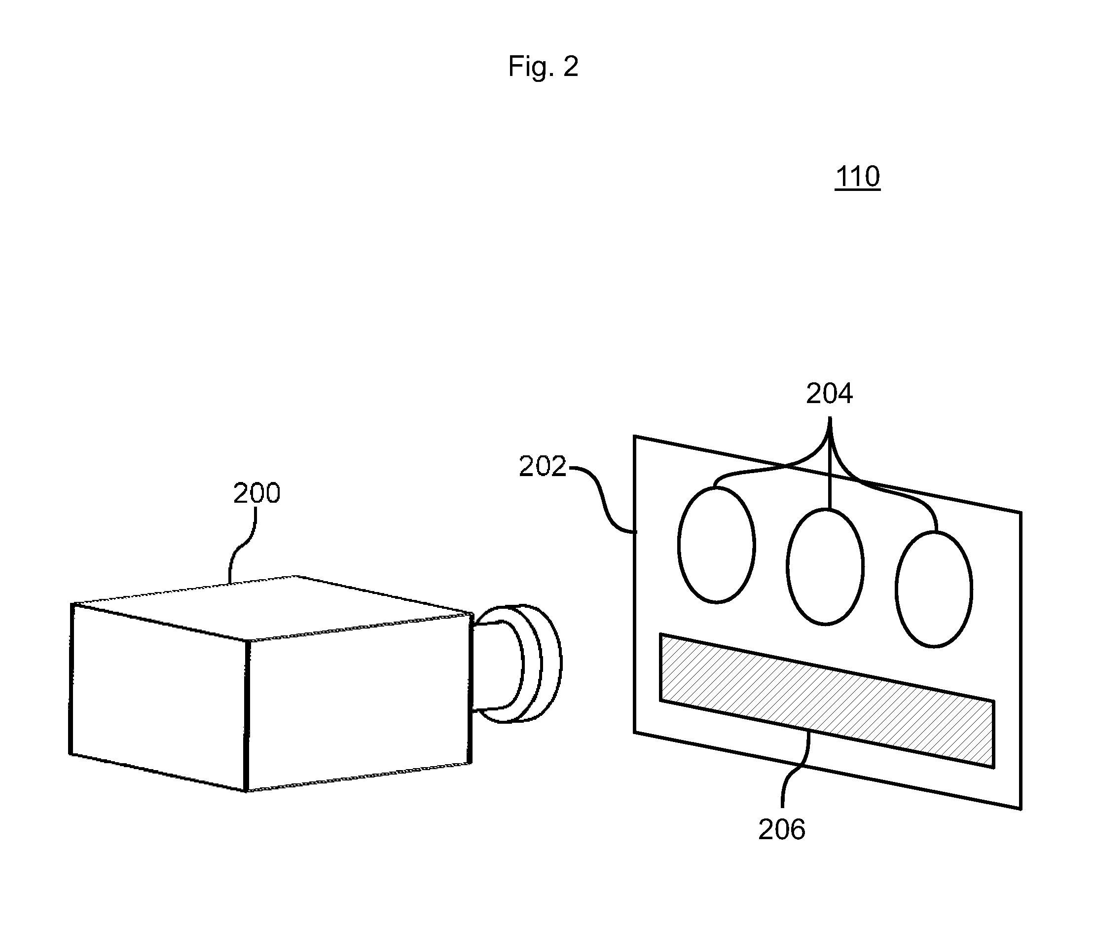
[0011]In some embodiments, the humidity indicator may be a desiccant that changes color cased on the humidity, and the electrical monitoring component may be a camera configured to take video data of the desiccant. The desiccant may be embedded in a card with printed registration ma

Problems solved by technology

Moisture is a well known problem for electrical systems.
The first issue with moisture and electrical systems is that water may short out an electrical circuit.
However, another problem caused by moisture is corrosion.
Electrical systems in outdoor or non sheltered installations are particularly exposed to conditions that tend to cause physical defects in the system.
For example, extreme temperature fluctuations, extremes in humidity, water intrusion, fouling by debris and being disturbed by animals are just a few of the problems that can affect an electrical system deployed outdoors.
When an electrical system is deployed in a remote location, access is generally limited by the remoteness of that location, and so an electrical system tends to lack regular examination and maintenance.
When combining a lack of maintenance with an outdoor installation, electrical systems can suffer a high failure rate.
However, as a practical matter, an electrical system cannot be completely sealed because the system needs maintenance, updating, repair and the like.
Permitting moisture in the form of humidity or liquids to contact the metal conductors of the electrical system can cause the metal circuits to corrode and eventually fail.
And galvanic corrosion is a well known issue that arises when dissimilar metals are able to exchange ions via direct contact or a liquid pathway.
This can particularly be a problem where connectors, cables, wires, traces, solder joints and the like are made from different metals and are exp

Method used


Image

  • System and method for remote monitoring of equipment moisture exposure
  • System and method for remote monitoring of equipment moisture exposure
  • System and method for remote monitoring of equipment moisture exposure

Examples


Embodiment Construction

[0020]Illustrative embodiments of the present principles are disclosed herein. However, techniques, systems and operating structures in accordance with the present principles may be embodied in a wide variety of forms and modes, some of which may be different from those in the disclosed embodiment. Consequently, the specific functional details disclosed herein are merely representative, yet in that regard, they are deemed to afford the best embodiment for purposes of disclosure and to provide a basis for the claims herein which define the scope of the present principles.

[0021]Some elements of the present principles are illustrated as modules for performing described functions. While these modules may be described in terms of software implementations, any hardware, or combination of hardware and software may be used to implement the present principles without deviating from the scope or spirit thereof.

[0022]Moreover, well known methods and procedures for both carrying out the objectives


PUM


Abstract

The presented principles are directed to an apparatus for monitoring humidity exposure of system components, with the apparatus having sensor modules for collecting environmental data and a monitoring module with a humidity indicator and an electrical monitoring component sealed from the environment that reads a physical change in the humidity indicator to determine the humidity of the environment. An installation computer may transmit the humidity data and sensor readings, wirelessly or otherwise, to a central monitoring station for processing and storage. The humidity indicator may be disposed within an enclosure to determine the humidity within that enclosure. The humidity indicator may also be a desiccant that changes color cased on the humidity, and the electrical monitoring component may be a camera configured to take video data of the desiccant.

Description


Claims


Application Information

Patent Timeline
Owner SCAPIER BRUCE
Why Eureka
Try Eureka