Reference current source circuit and system

Inactive Publication Date: 2013-05-02
IPGOAL MICROELECTRONICS (SICHUAN) CO LTD
View PDF8 Cites 1 Cited by
  • Summary
  • Abstract
  • Description
  • Claims
  • Application Information

AI Technical Summary

Benefits of technology

[0009]Compared with conventional arts, the reference current source circuit and system of the present invention output the reference current only related to the capacitance ratio, generate the reference current without any externally attached resistance, has a simple structure and also reduce a chip cost.

Problems solved by technology

Thus, in order to generate a highly precise reference current source, it is required to externally attach a resistor or to rectify the resistance value through a calibration mechanism of a back-end test, whereas both add up a cost of a chip.
Based on above analysis, the conventional reference current source needs an externally attached resistor to generate the highly precise reference current source and thus increases the cost of the chip.

Method used


Image

  • Reference current source circuit and system
  • Reference current source circuit and system
  • Reference current source circuit and system

Examples


Example

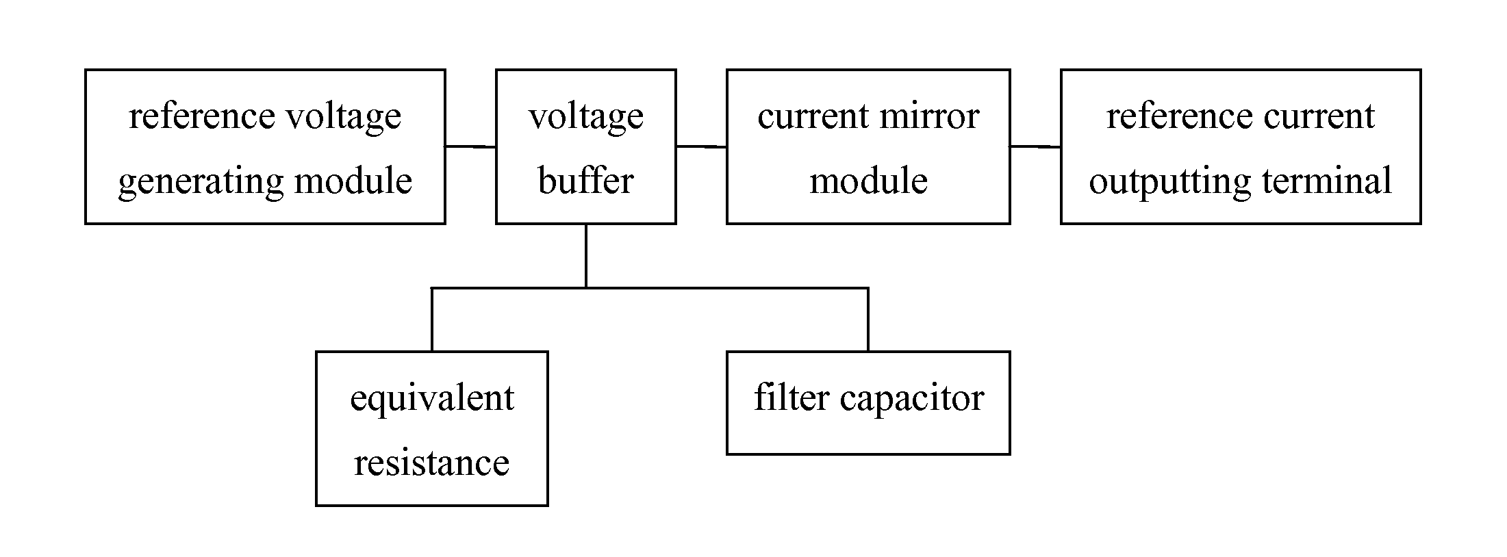
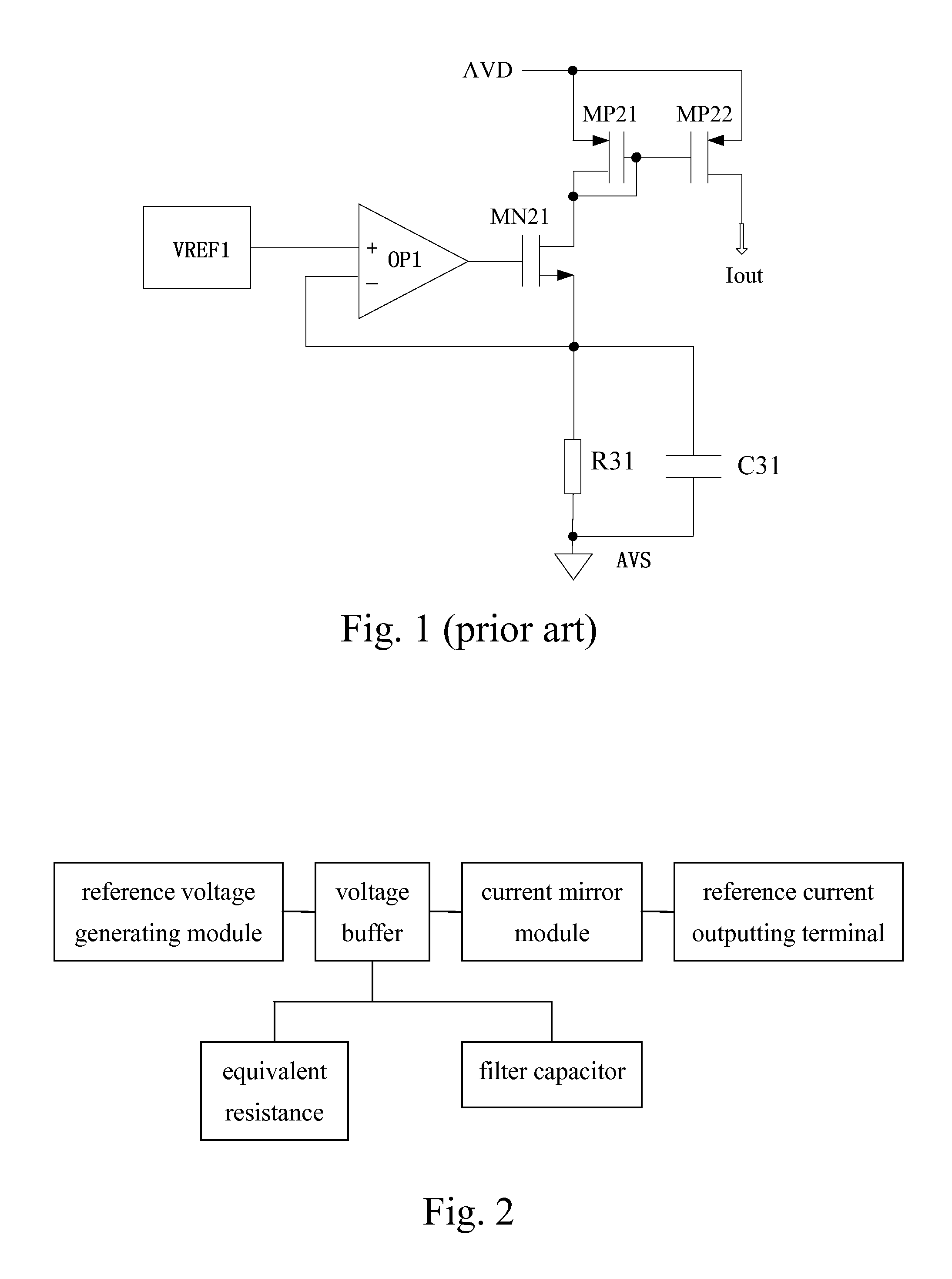
[0014]Referring to FIGS. 2 and 3 of the drawings, a reference current source circuit and its system according to a preferred embodiment of the present invention are illustrated, comprising a reference voltage generating module VREF, a voltage buffer connected to the reference voltage generating module VREF, an equivalent resistor connected to the voltage buffer, a filter capacitor C1 connected to the voltage buffer, a current mirror module connected to the voltage buffer and a reference current outputting terminal lout connected to the current mirror module, wherein the voltage buffer comprises an operational amplifier OP and a first FET M1 connected to the operational amplifier OP; the current mirror module comprises a second FET M2 and a third FET M3 connected to the second FET M2; the equivalent resistor comprises an oscillator OSC, a fourth FET M4 connected to the oscillator OSC, a fifth FET M5 connected to the oscillator OSC and a capacitor C2 connected to the fourth FET M4 and th


PUM


Abstract

A reference current source circuit includes a reference voltage generating module, a voltage buffer, an equivalent resistance, a filter capacitor, a current mirror module and a reference current outputting terminal. The voltage buffer includes an operational amplifier and a first FET. The current mirror module includes a second FET and a third FET. The equivalent resistor includes an oscillator, a fourth FET, a fifth FET and a capacitor connected to the fourth FET and the fifth FET. The oscillator is for generating a clock signal whose frequency is related to a charging and discharging capacitor in the oscillator to control charging and discharging of the capacitor in the equivalent resistance. The reference current outputting terminal is for outputting a reference current only related to a capacitance ratio of the capacitor to the charging and discharging capacitor. A reference current source system is further disclosed.

Description


Claims


Application Information

Patent Timeline
Owner IPGOAL MICROELECTRONICS (SICHUAN) CO LTD
Why Eureka
Try Eureka