Wireless energy transfer systems

Inactive Publication Date: 2013-05-16
COLUMBIA INSURANCE CO
View PDF29 Cites 239 Cited by
  • Summary
  • Abstract
  • Description
  • Claims
  • Application Information

AI Technical Summary

Benefits of technology

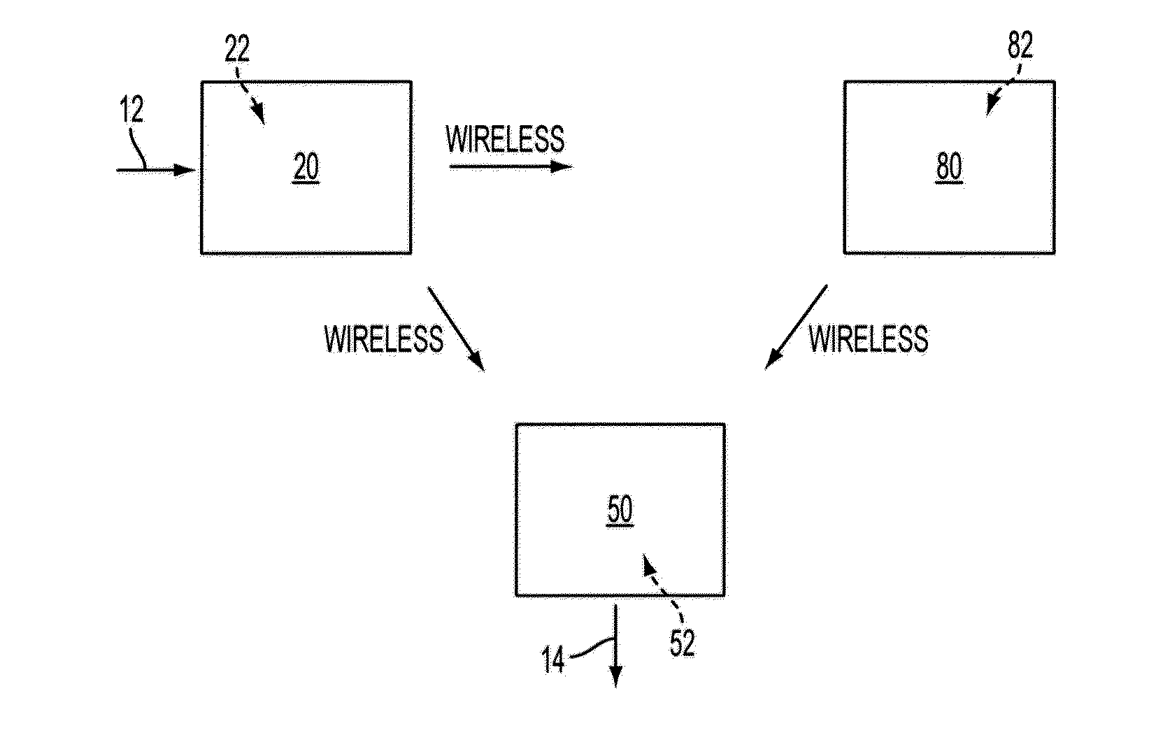
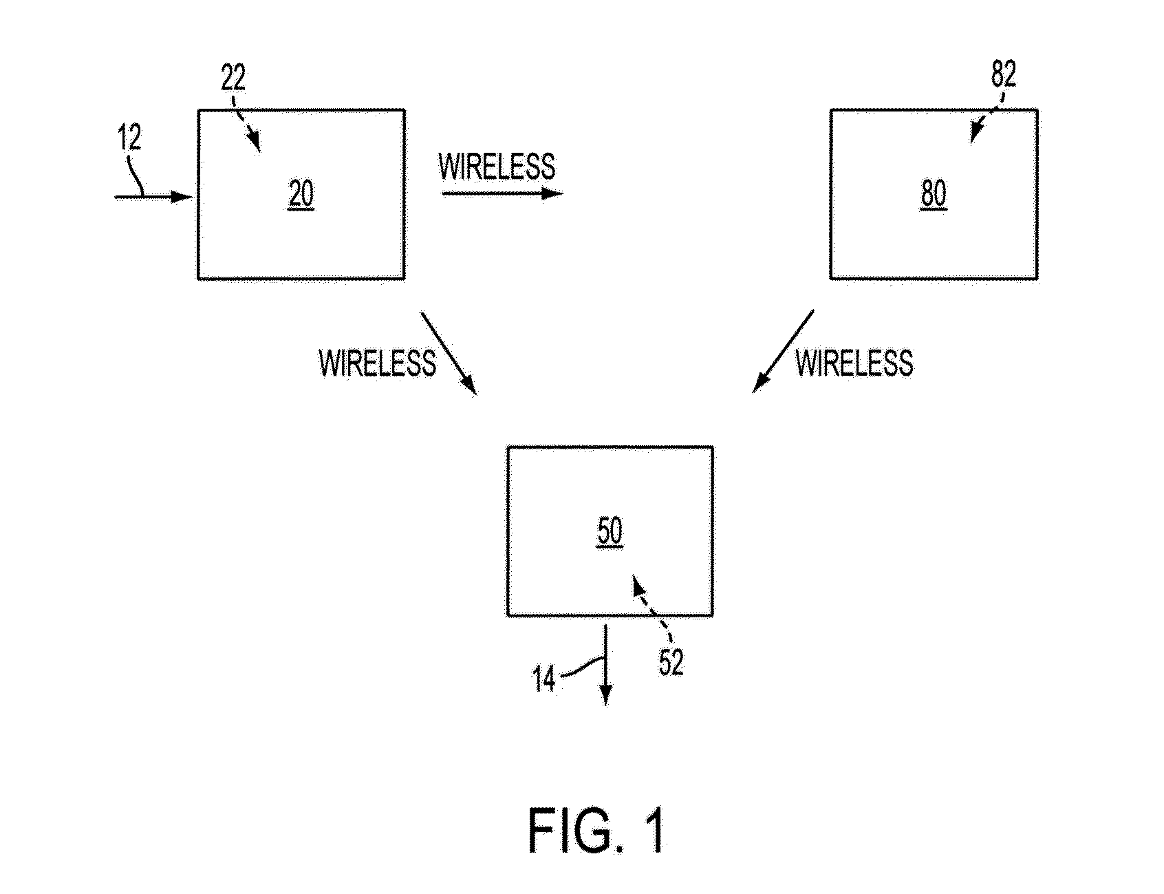
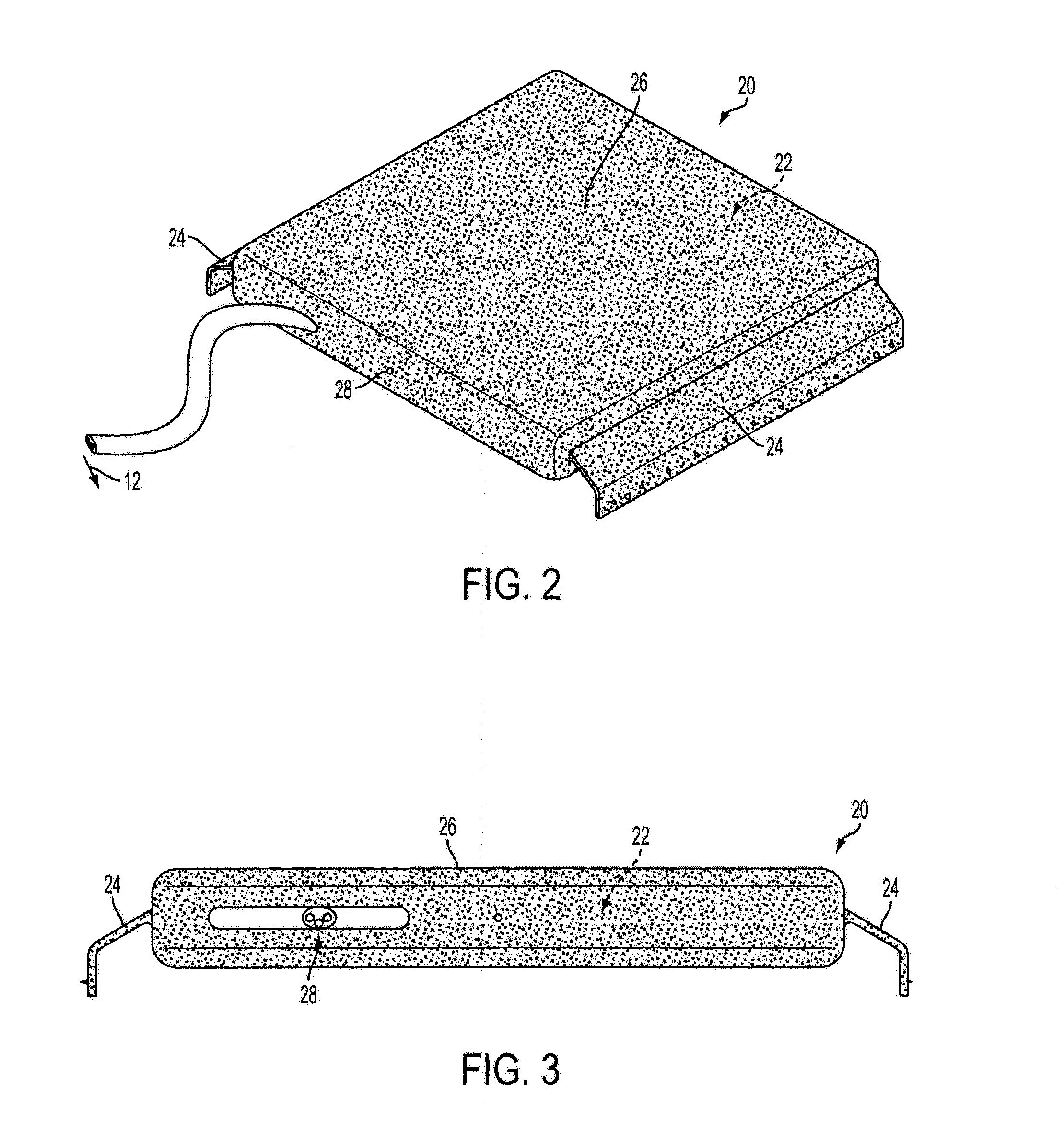
[0008]It is contemplated that the power receptor can receive energy from a power emitter and can convert a portion of that energy to electric power for powering or charging an electrically powered device. In a further aspect, it is also contemplated that the system and method disclosed herein can comprise at least one passive power emitter mountable at a select locations within the building structure that is configured to be inductively coupled to energy wirelessly resonating from the

Problems solved by technology

Conventional electronic devices so common in today's world problematically require associated cords and cables for charging and/or operating the electronic devices.
A substantial demand exists however for a wireles

Method used


Image

  • Wireless energy transfer systems
  • Wireless energy transfer systems
  • Wireless energy transfer systems

Examples


Embodiment Construction

[0016]The present invention can be understood more readily by reference to the following detailed description, examples, drawings, and claims, and their previous and following description. However, before the present devices, systems, and / or methods are disclosed and described, it is to be understood that this invention is not limited to the specific devices, systems, and / or methods disclosed unless otherwise specified, as such can, of course, vary. It is also to be understood that the terminology used herein is for the purpose of describing particular aspects only and is not intended to be limiting.

[0017]The following description of the invention is provided as an enabling teaching of the invention in its best, currently known embodiment. To this end, those skilled in the relevant art will recognize and appreciate that many changes can be made to the various aspects of the invention described herein, while still obtaining the beneficial results of the present invention. It will al


PUM


Abstract

An inductively coupled power system for use in a structure having at least one power emitter electrically coupled to an external electrical power source and at least one power receptor directly coupled to a load with direct electrical connections, which is configured to inductively couple to energy wirelessly resonating from the at least one power emitter and to convert the inductively received energy to a desired output energy configuration for supply to the load. The system can also include at least one passive power emitter that is configured to be inductively coupled to energy wirelessly resonating from the at least one power emitter or the at least one passive power emitter.

Description


Claims


Application Information

Patent Timeline
Owner COLUMBIA INSURANCE CO
Why Eureka
Try Eureka