Fluid reservoir having a heating reserve bowl

a technology of flue gas and reservoir, which is applied in the field of flue gas reservoir, can solve the problems of not necessarily guaranteeing operation, complex solutions, and high cost, and achieve the effects of convenient and fast operation, convenient operation and complete controllability

Inactive Publication Date: 2013-05-23
MGI COUTIER SA
View PDF2 Cites 3 Cited by
  • Summary
  • Abstract
  • Description
  • Claims
  • Application Information

AI Technical Summary

Benefits of technology

This patent describes a device called a holding cup used to hold a liquid like a reduction agent during operations. Unlike other methods, it does not require any pumps, which makes it more efficient than traditional methods. Even when there are slope situations, the cup remains stable and prevents excessive cooling. A thermistor placed within the cup helps control the heating process. By combining these two components, the device allows for precise and controlled operation over varying environmental factors.

Problems solved by technology

The technical problem addressed in this patent is how to efficiently heat up reducing agents in a motor vehicle's emission control devices during cold weather conditions while ensuring proper functioning of the reduction agents.

Method used


Image

  • Fluid reservoir having a heating reserve bowl
  • Fluid reservoir having a heating reserve bowl
  • Fluid reservoir having a heating reserve bowl

Examples


Embodiment Construction

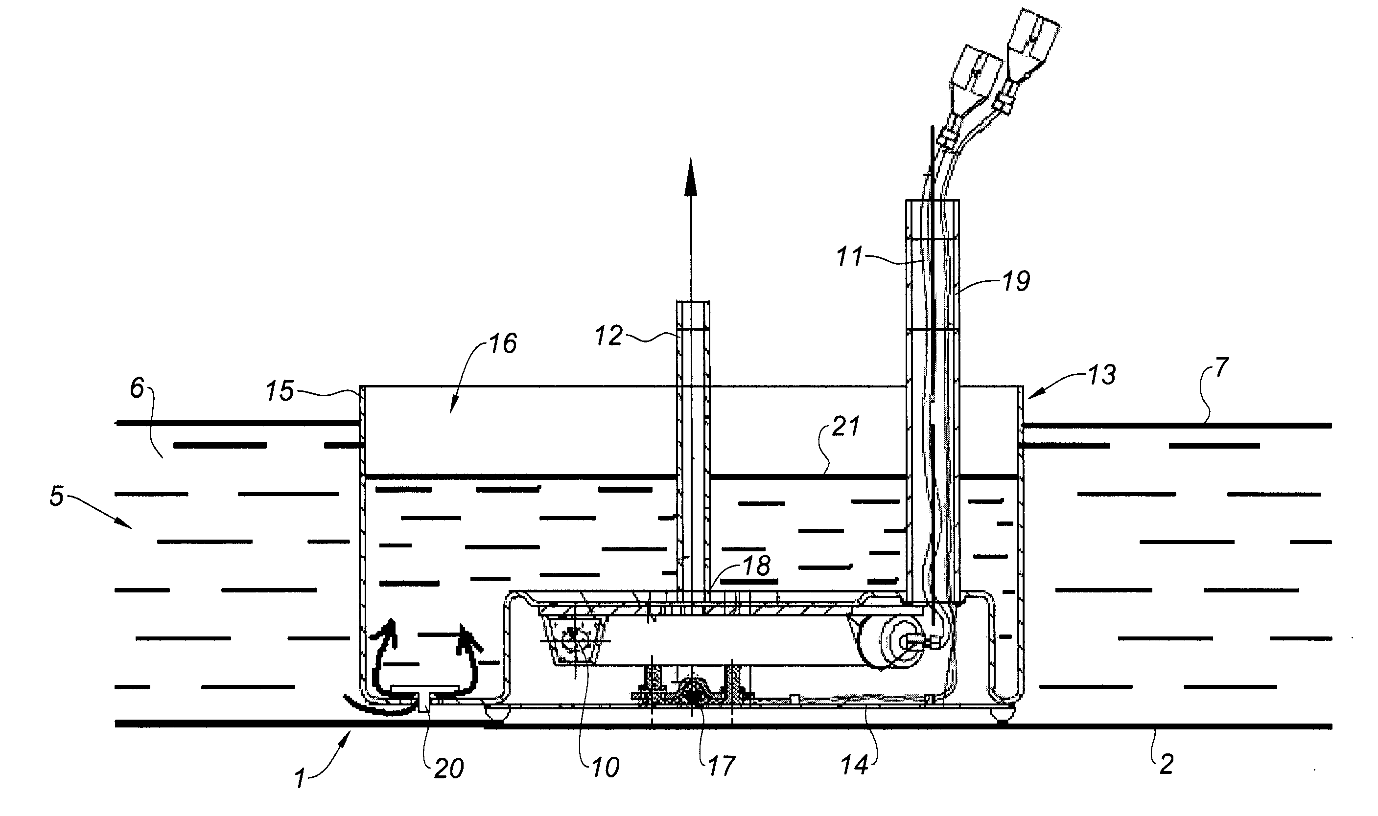
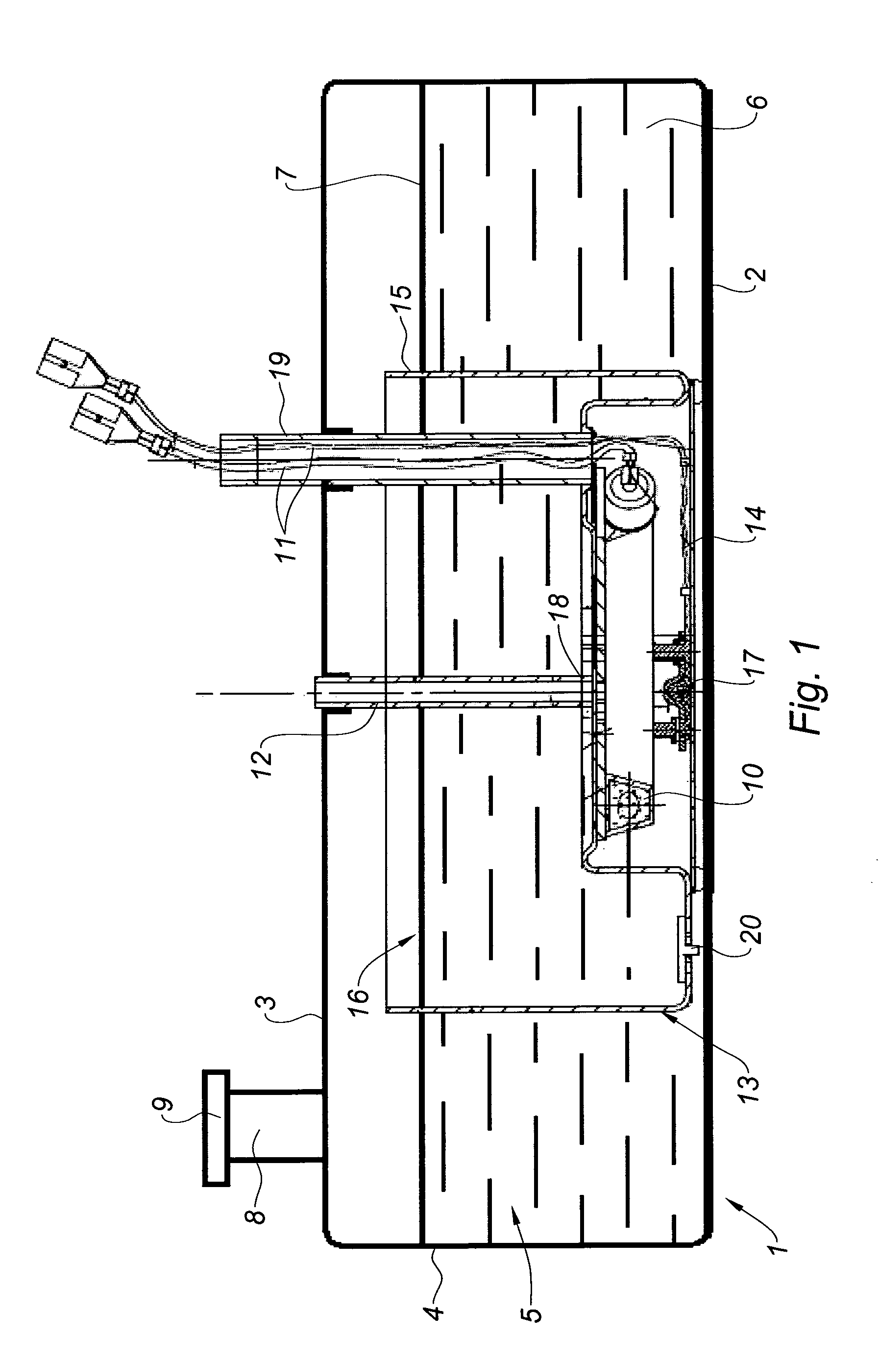
[0024]In the drawing, reference 1 designates, in its entirety, a reducing agent reservoir, which comprises a lower wall 2, an upper wall 3 and a side wall 4, which delimit an interior volume 5 of said reservoir 1.

[0025]The reservoir 1 contains, during use, a certain quantity of reducing agent 6, the level of which is indicated in 7. A filling orifice 8, placed on the upper wall 3 and normally covered by a plug 9, makes it possible to introduce the reducing agent 6 into the reservoir 1.

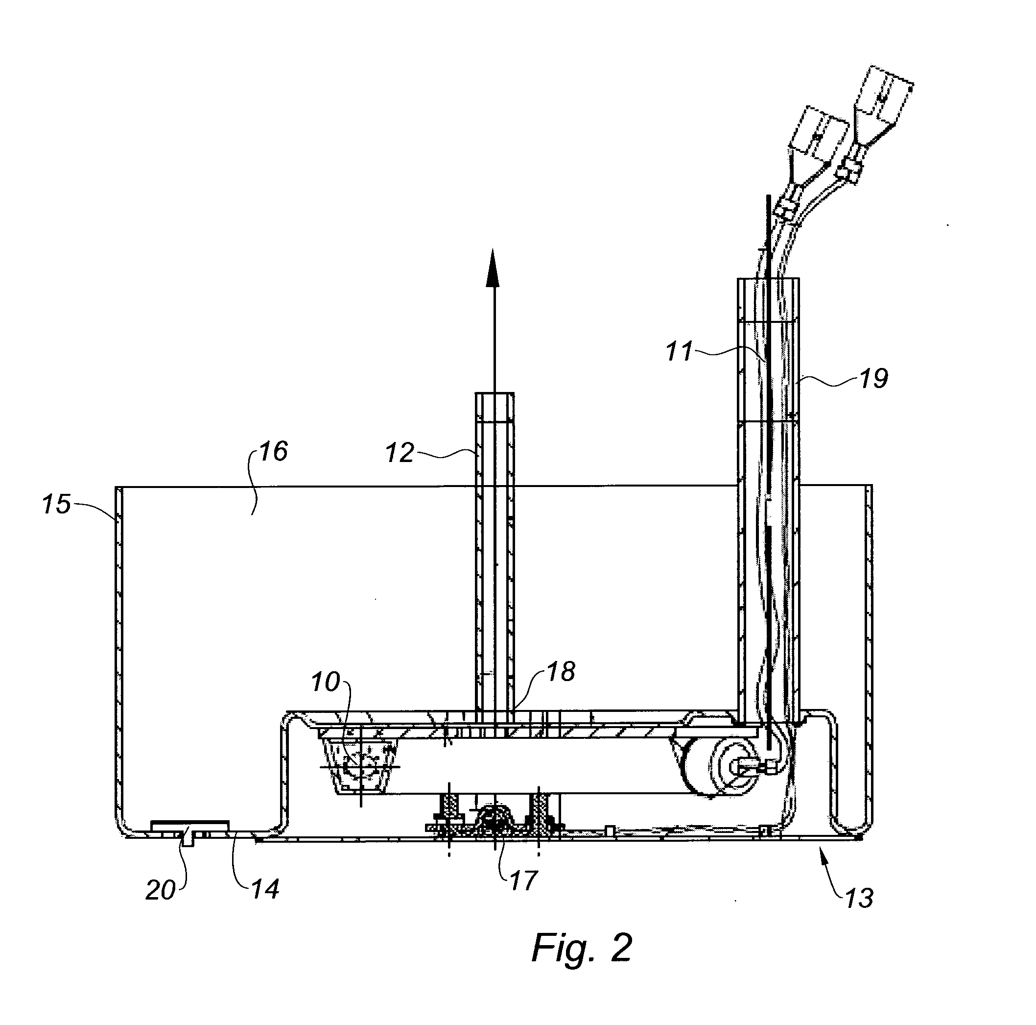
[0026]In its lower portion, the reservoir 1 is equipped with a heating element 10 of the electric type, powered by electrical conductors 11. The heating element 10 is provided to at least partially thaw the reducing agent 6 in order to allow it to be withdrawn by a suction pipe 12, even at low temperatures. The suction pipe 12 is oriented towards a pump (not shown) using which the reducing agent 6 is withdrawn from the reservoir 1 and sent towards an injector, which distributes the reducing agent in the e


PUM


Abstract

The invention relates in particular to a reservoir for a urea-based reducing agent, with an integrated electric heating element, usable on a heat engine vehicle for pollution control. The heating element (10) provided to thaw the reducing agent (6) is placed inside a cavity (16) delimited by a bowl (13), itself placed inside the reservoir (1). The cavity (16) of the bowl (13) communicates with the inner volume (5) of the reservoir by a valve (20). A suction pipe (12) for the reducing agent is submerged in the cavity (16) of the bowl (13), the starting point (18) of said pipe being situated near the heating element (10). Operation is thus guaranteed when the vehicle is under sloping and inclined conditions, and also in case of freeze.

Description


Claims


Application Information

Patent Timeline
Owner MGI COUTIER SA
Why Eureka
Try Eureka