Method of Determining a Radio Link Failure Associated with a Handover of a User Equipment for a Source Access Node to a Target Access Node, Access Node for Determining a Radio Link Failure Associated with a Handover of a User Equipment from a Source Access Node to a Target Access Node, and User Equipment

a radio link and user equipment technology, applied in the direction of electrical equipment, network traffic/resource management, connection management, etc., can solve the problems of significant degradation of the service negatively affecting the user experience, and the performance of the access network. achieve the effect of improving the performance of the access network

Inactive Publication Date: 2013-07-11
NOKIA SOLUTIONS & NETWORKS OY
View PDF6 Cites 18 Cited by
  • Summary
  • Abstract
  • Description
  • Claims
  • Application Information

AI Technical Summary

Benefits of technology

The technical effect that this technology improves how well it works for accessing networks like wireless LANs (WLAN).

Problems solved by technology

This patented technical problem addressed in this patents relates to optimally managing interference caused by wireless networks while ensuring efficient communication over different types of connections. Specifically, there can happen situations that require more effort than usual if one type of connection fails before other ones. Additionally, current methods only consider specific factors like signal quality metrics at certain times instead of comprehensive consideration across all possible scenarios.

Method used


Image

  • Method of Determining a Radio Link Failure Associated with a Handover of a User Equipment for a Source Access Node to a Target Access Node, Access Node for Determining a Radio Link Failure Associated with a Handover of a User Equipment from a Source Access Node to a Target Access Node, and User Equipment
  • Method of Determining a Radio Link Failure Associated with a Handover of a User Equipment for a Source Access Node to a Target Access Node, Access Node for Determining a Radio Link Failure Associated with a Handover of a User Equipment from a Source Access Node to a Target Access Node, and User Equipment
  • Method of Determining a Radio Link Failure Associated with a Handover of a User Equipment for a Source Access Node to a Target Access Node, Access Node for Determining a Radio Link Failure Associated with a Handover of a User Equipment from a Source Access Node to a Target Access Node, and User Equipment

Examples


Embodiment Construction

[0085]The illustration in the drawings is schematic. It is noted that in different figures, similar or identical elements are provided with the same reference signs.

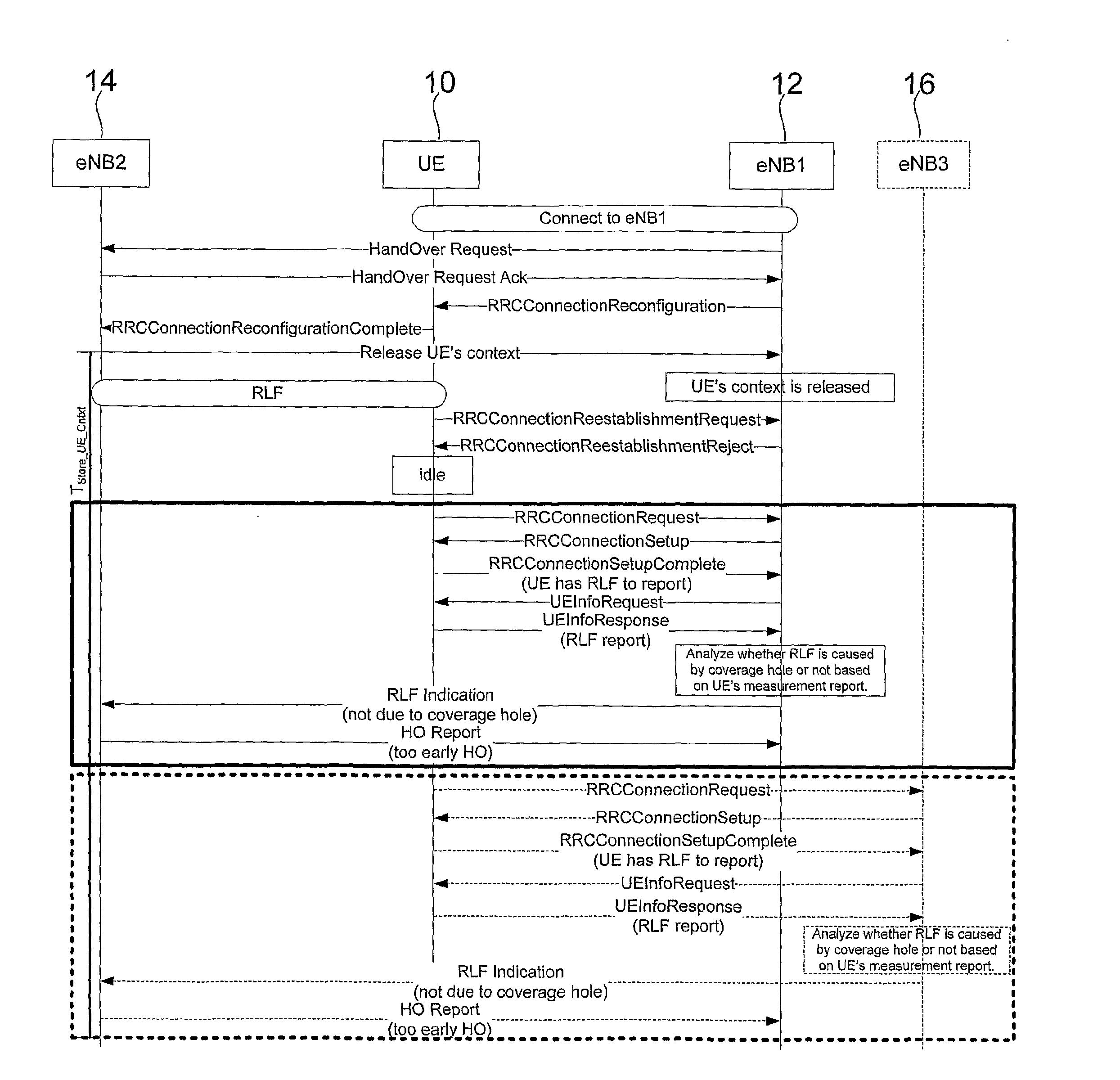
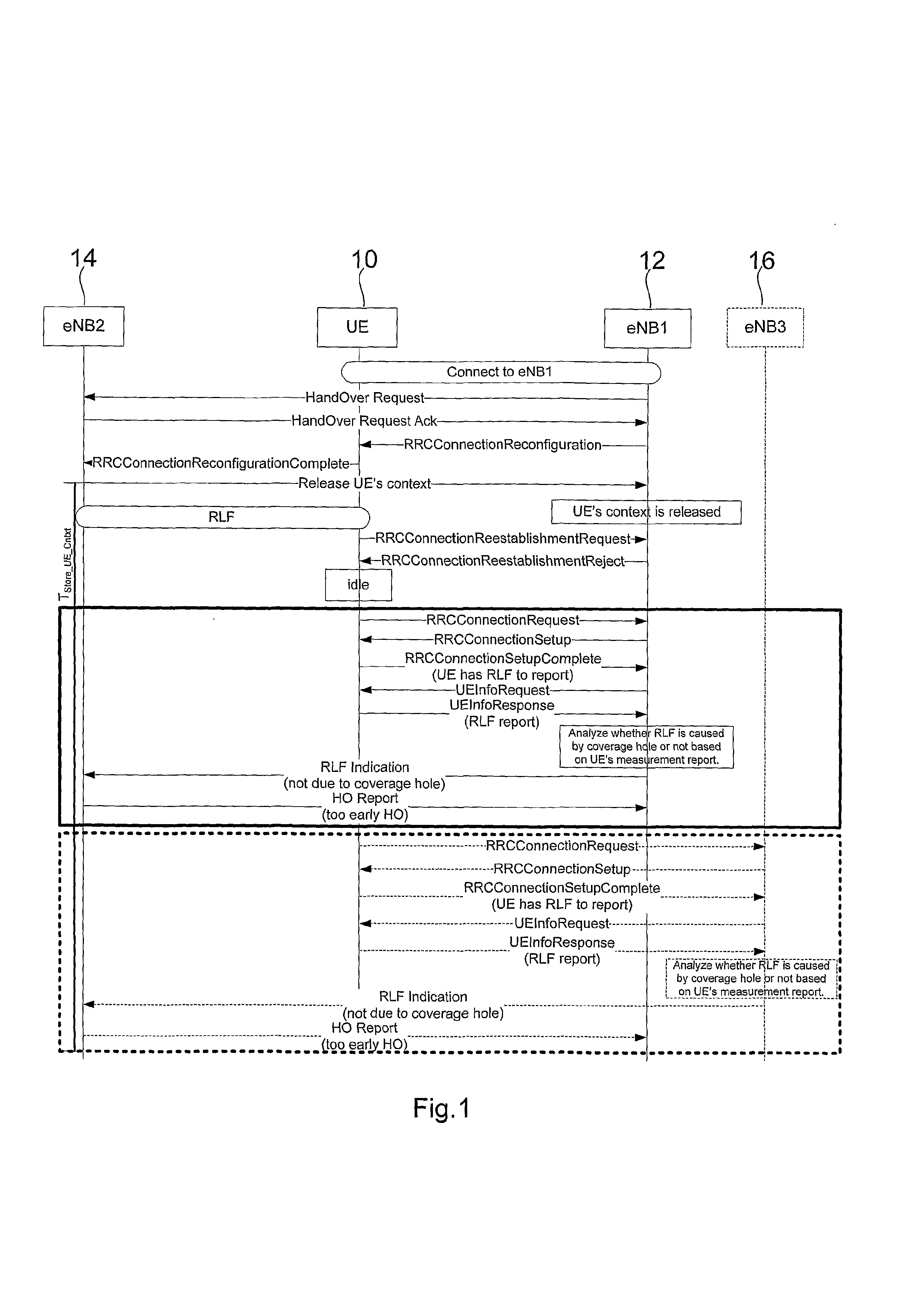
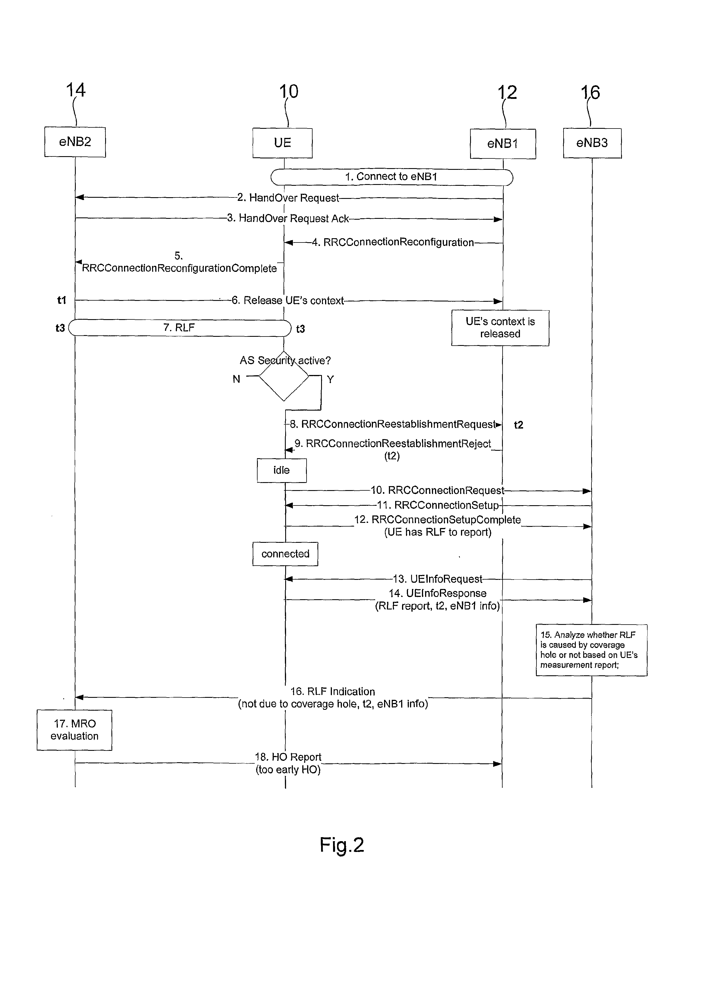
[0086]In the following, methods of determining a RLF based on absolute time information and relative time information will be explained. For explanation purposes, it will be assumed that a too early handover RLF has occurred subsequent to a handover from a user equipment from a source access node to a target access node. However, the described analysis of the kind of RLF will also apply to other kind of radio link failures such as a too late handover or a handover to a wrong cell. The communications architecture shown in FIG. 2, 3 are similar to the communications architecture shown in FIG. 1.

[0087]Referring to FIG. 2, a user equipment 10 is initially attached to a source access node 12 as indicated by step 1. Handover negotiations between the user equipment 10, the source access node 12 and the target access node 14 are de


PUM


Abstract

A method of determining a radio link failure associated with a handover of a user equipment from a source access node to a target access node includes acquiring a first information about a time associated with the user equipment communicating with an access node for establishing a connection associated with the handover and a second information indicating the access node with which the user equipment communicates for establishing a connection subsequent to the radio link failure, and determining the radio link failure based on the acquired first and/or second information.

Description


Claims


Application Information

Patent Timeline
Owner NOKIA SOLUTIONS & NETWORKS OY
Why Eureka
Try Eureka