Electronic device

Inactive Publication Date: 2013-08-01
PANASONIC INTELLECTUAL PROPERTY MANAGEMENT CO LTD
View PDF6 Cites 0 Cited by
  • Summary
  • Abstract
  • Description
  • Claims
  • Application Information

AI Technical Summary

Benefits of technology

[0010]An electronic device according to the present disclosure eliminates the effect of rush current when it is connected to an external device while power is supplied from an external power supply, and effectively utilizes the supply capacity of the external power supply.

Problems solved by technology

A problem that can occur when this happens is that the rush current causes a temporary drop in the supply voltage, and this drop in the supply voltage causes the power to turn off.
However, the conventional electronic device described above has a problem that if the rush current is high while an external device is connected, the capacity of the external power supply cannot be used effectively.
Depending on the actual external power supply capacity and the threshold level of the input current limit, unnecessary protection may thus be applied.
As a result, only current up to the reduced limit is supplied, and it takes more time to charge the battery, so that effectively using the capacity of the external power supply may not be possible.

Method used


Image

  • Electronic device
  • Electronic device
  • Electronic device

Examples


Example

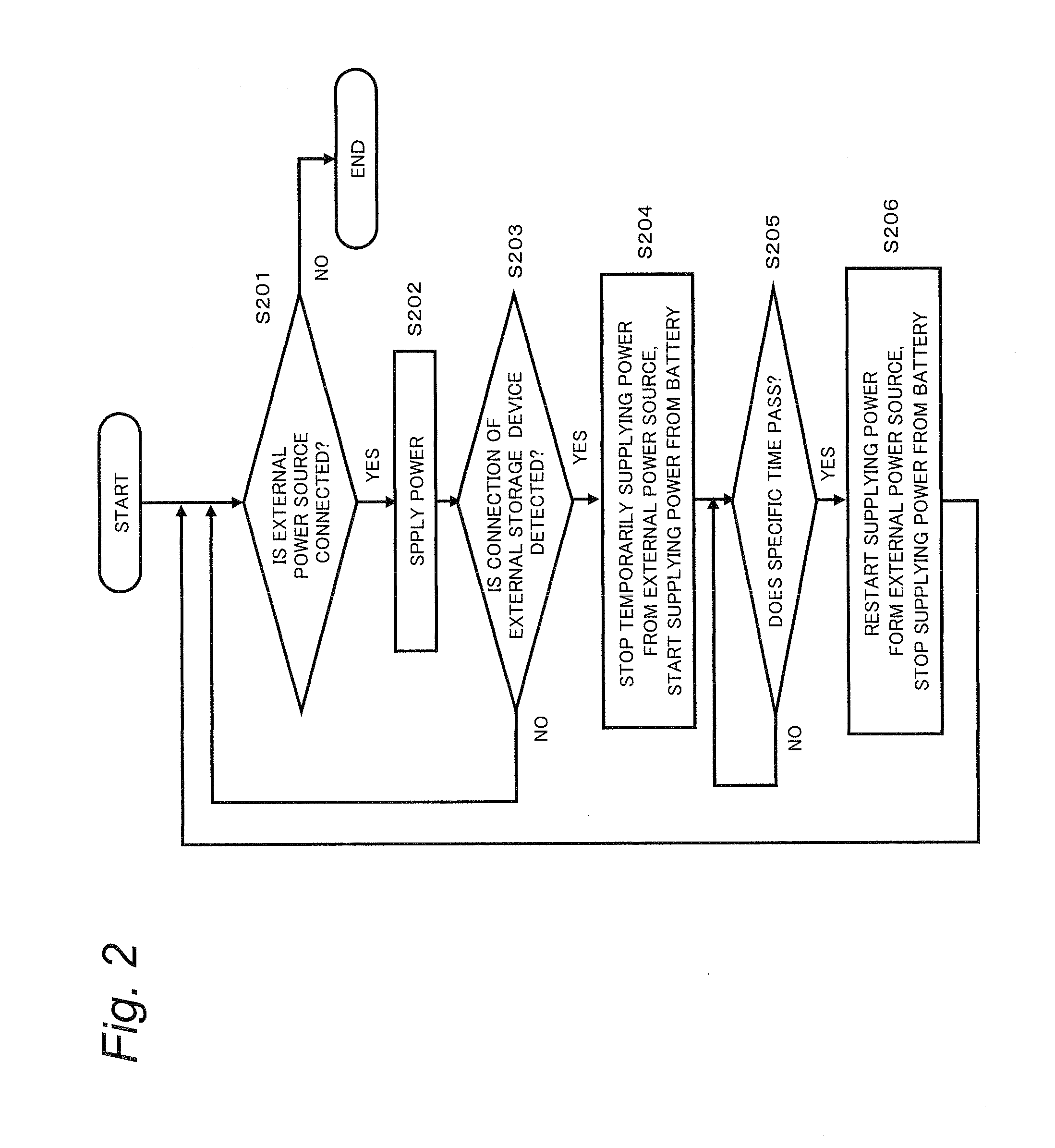
[0017]According to a first embodiment, when an electronic device is connected to an external device while power is being supplied to the electronic device from an external power supply, the electronic device detects connection of the external device and temporarily stops supply of power from the external power supply while a rush current is flowing to the external device. As a result, the electronic device prevents a drop in the voltage of the external power supply caused by the rush current occurring when the external device is connected. The configuration and operation of an electronic device according to this embodiment are described below.

1. Configuration of Electronic Device

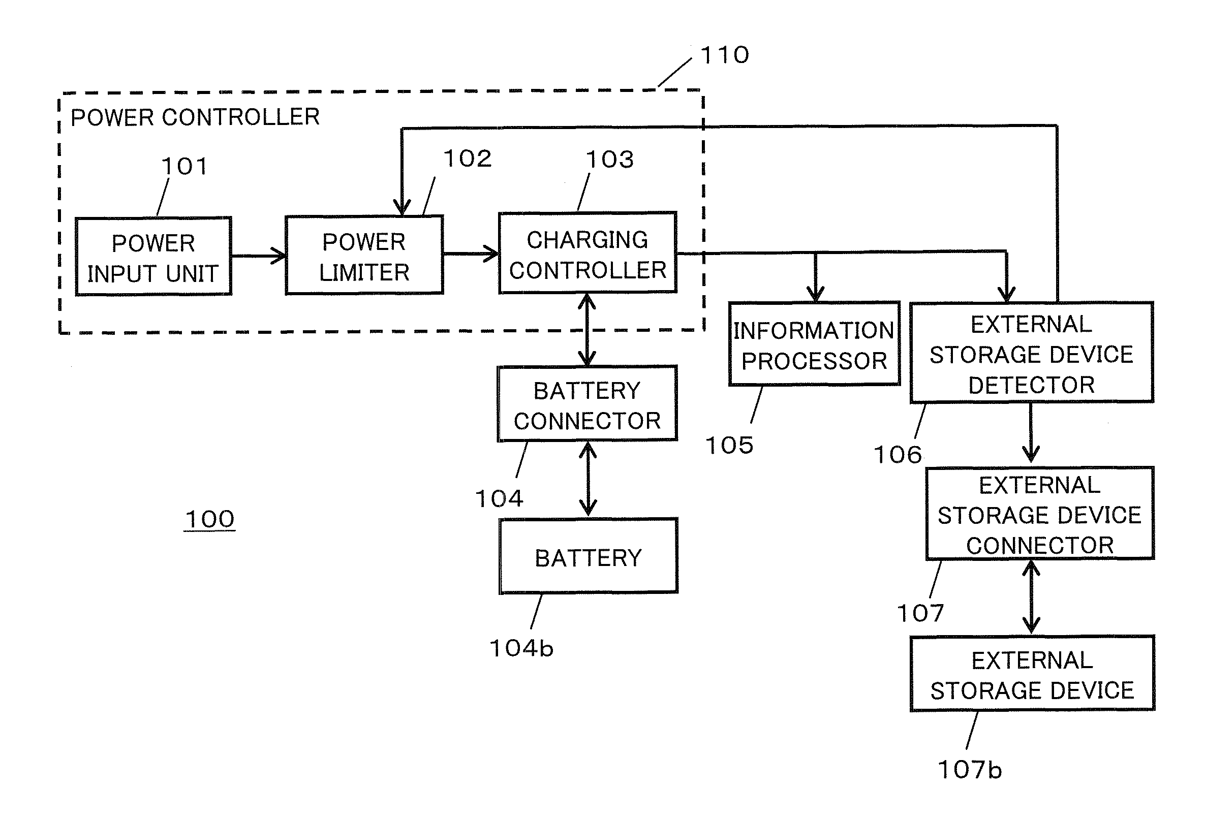
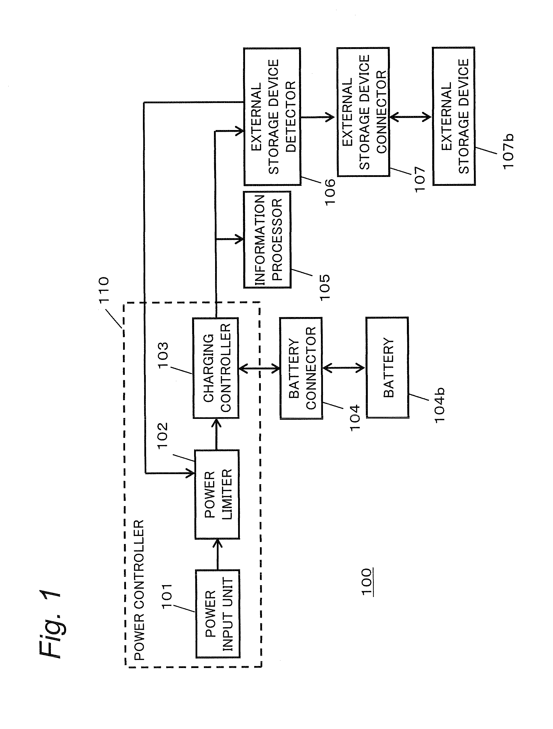
[0018]The configuration of the electronic device is described below with reference to FIG. 1. FIG. 1 is a block diagram showing the configuration of the electronic device. The electronic device 100 has a power input unit 101, a power limiter 102, a charging controller 103, a battery connector 104, an informatio


PUM


Abstract

An electronic device includes a power input unit through which power from an external power source can be input, a battery connector that is electrically connectable to a battery, a device connector that is electrically connectable to a removable external device, and a power controller that controls supply of power to the external device from the external power source and the battery. When the external device is connected to the connector, the power controller stops supplying power from the power input unit and supplies power from the battery to the external device, before supplying power from the external power source to the external device.

Description


Claims


Application Information

Patent Timeline
Owner PANASONIC INTELLECTUAL PROPERTY MANAGEMENT CO LTD
Why Eureka
Try Eureka