Method for controlling a hybrid traction assembly and hybrid vehicle controlled according to such a method
a hybrid traction and hybrid vehicle technology, applied in the direction of automatic control systems, process and machine control, instruments, etc., can solve the problems of shortening the service life of storage devices, prior art controlling methods which are common to many vehicles, and not being desirable from many standpoints
- Summary
- Abstract
- Description
- Claims
- Application Information
AI Technical Summary
Benefits of technology
Problems solved by technology
Method used
Image
Examples
first embodiment
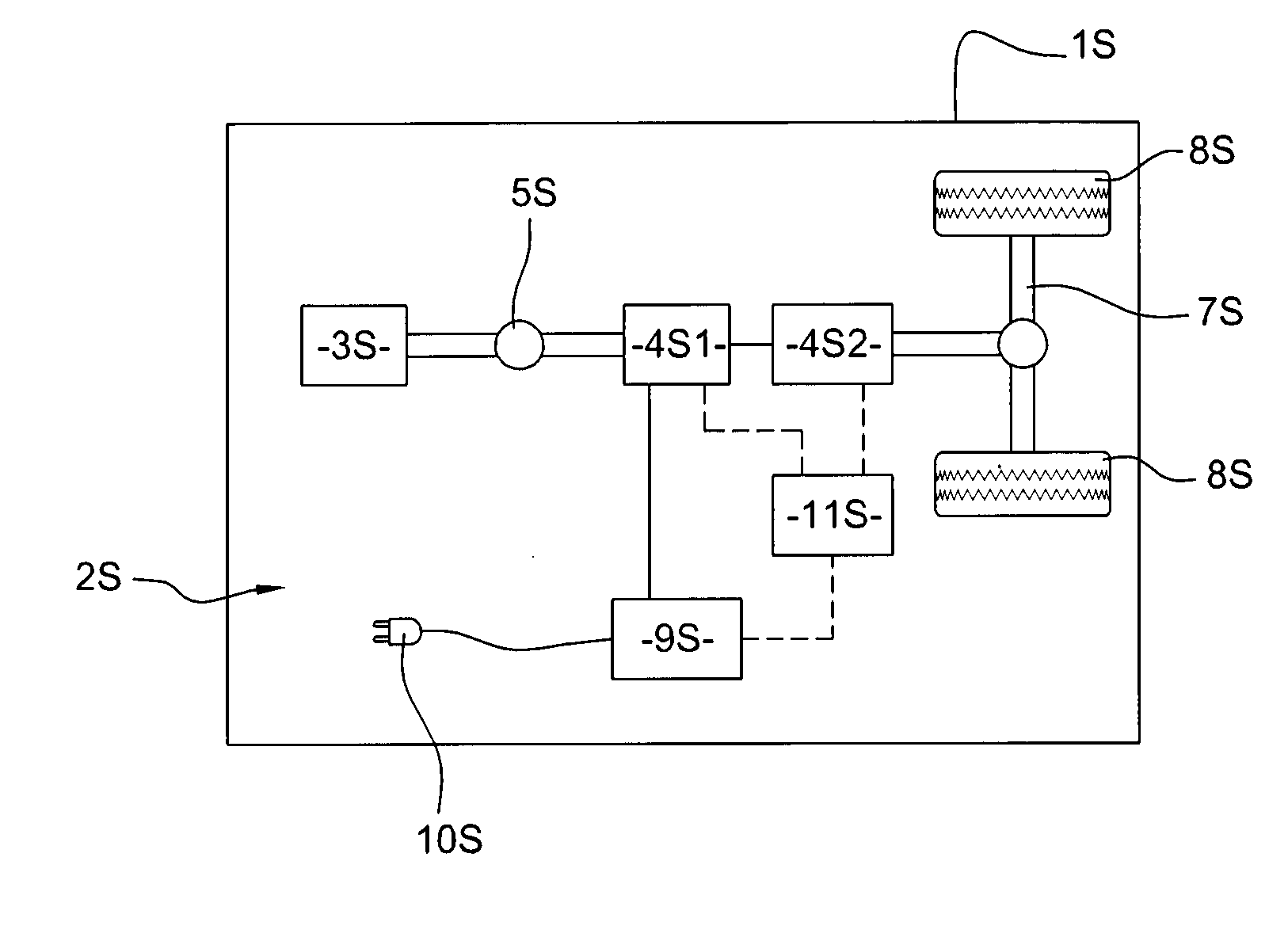
[0037]FIG. 1 depicts a hybrid vehicle 1 S according to the present invention, for instance an industrial vehicle, which has a hybrid traction assembly 25. Hybrid vehicle 1 is of the series hybrid type. Hybrid traction assembly 2S comprises an internal combustion engine 3S and two electric machines 4S1, 4S2. The internal combustion engine 3S is coupled to one of the electric machine 4S1 which operates mainly as a generator to produce electrical current. The second electric machine 4S2 mostly works as an electric traction motor, etc.
[0038]Advantageously, the electric machines 4S1, 4S2 can be reversible machines. They can for example be brushless direct current motors with permanent magnets, alternate current induction motors.
[0039]The second electric machine 4S2 can work as an electric generator, for generating electric regenerative energy when the hybrid vehicle 1 S slows down or brakes. When any decelerating command is given, e.g. when the brake pedal is depressed, this electric machin
second embodiment
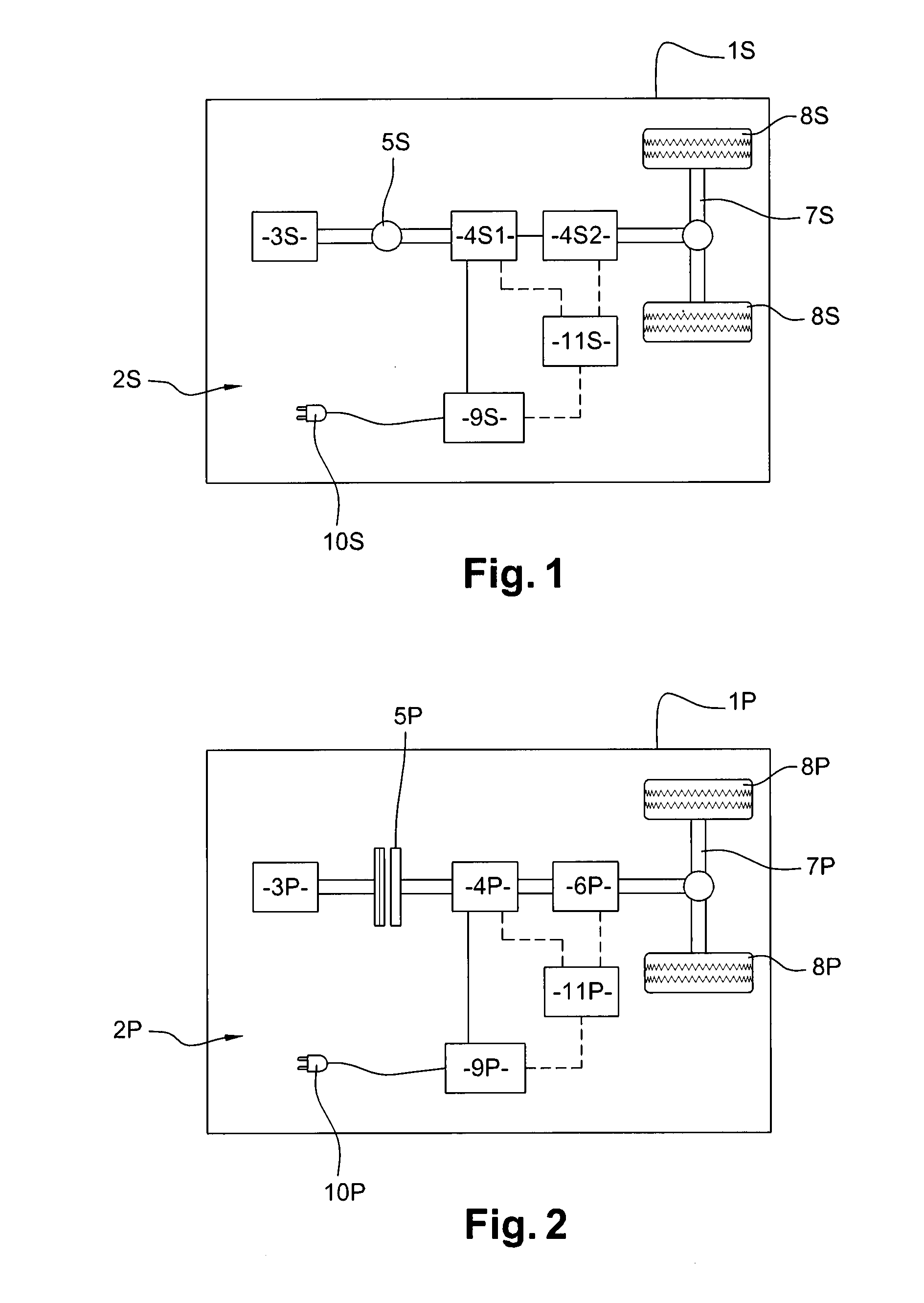
[0043]FIG. 2 depicts a hybrid vehicle 1 P according to the present invention, for instance an industrial vehicle, which has a hybrid traction assembly 2P. Most of the parts of hybrid vehicle 1 P have structures and / or functions that are quite similar to the structures and / or functions of the corresponding parts of hybrid vehicle 1 S depicted on FIG. 1,
[0044]Hence, the afore-stated description of hybrid vehicle 1 S given in relation to FIG. 1 can be transposed to hybrid vehicle 1 P of FIG. 2, except for the hereafter-stated differences.
[0045]In most cases, the reference sign of a part of hybrid vehicle 1 P can be derived, by replacing suffix letter S by suffix letter P, from the reference sign of the part of hybrid vehicle 1 S that has the corresponding structure and / or function. One can thus define:
[0046]hybrid vehicle 1 P;
[0047]a hybrid traction assembly 2P;
[0048]an internal combustion engine 3P;
[0049]an electric machine 4P;
[0050]a transmission 6P:
[0051]wheel shafts 7P;
[0052]dri
PUM
 Abstract
Description
Claims
Application Information
 - R&D Engineer
- R&D Manager
- IP Professional
- Industry Leading Data Capabilities
- Powerful AI technology
- Patent DNA Extraction
Browse by: Latest US Patents, China's latest patents, Technical Efficacy Thesaurus, Application Domain, Technology Topic.
© 2024 PatSnap. All rights reserved.Legal|Privacy policy|Modern Slavery Act Transparency Statement|Sitemap


