Inkjet printing apparatus and control method thereof
a technology of printing apparatus and control method, which is applied in the direction of printing and other printing apparatus, can solve the problems of difficult to distinguish wet properties between the adhered ink and the hydrophilic surface, difficulty in drying ink in the ejection opening, and difficulty in ensuring the effect of water repellent treatment, etc., and achieves stable ejection and high speed
- Summary
- Abstract
- Description
- Claims
- Application Information
AI Technical Summary
Benefits of technology
Problems solved by technology
Method used
Image

Examples
first embodiment
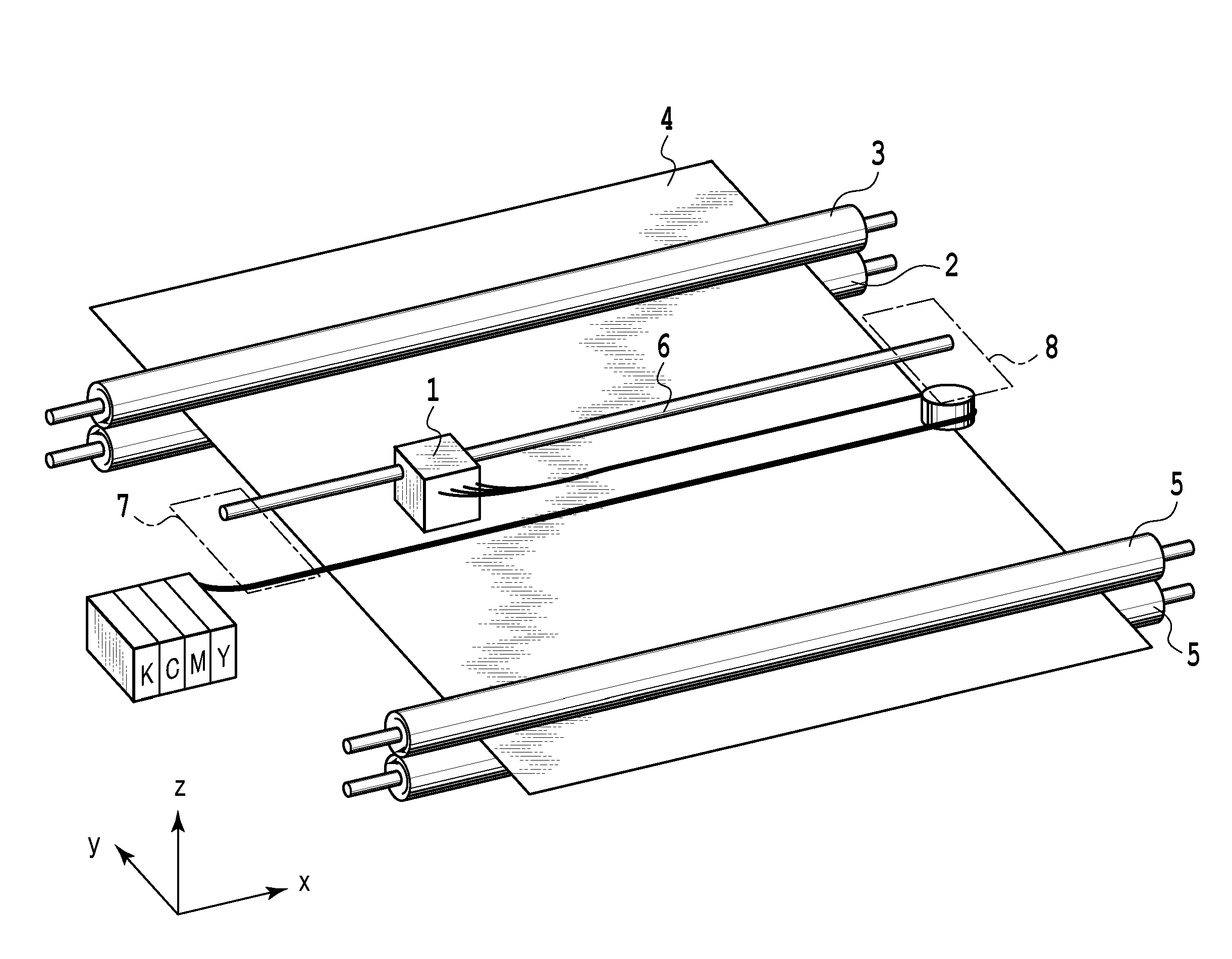
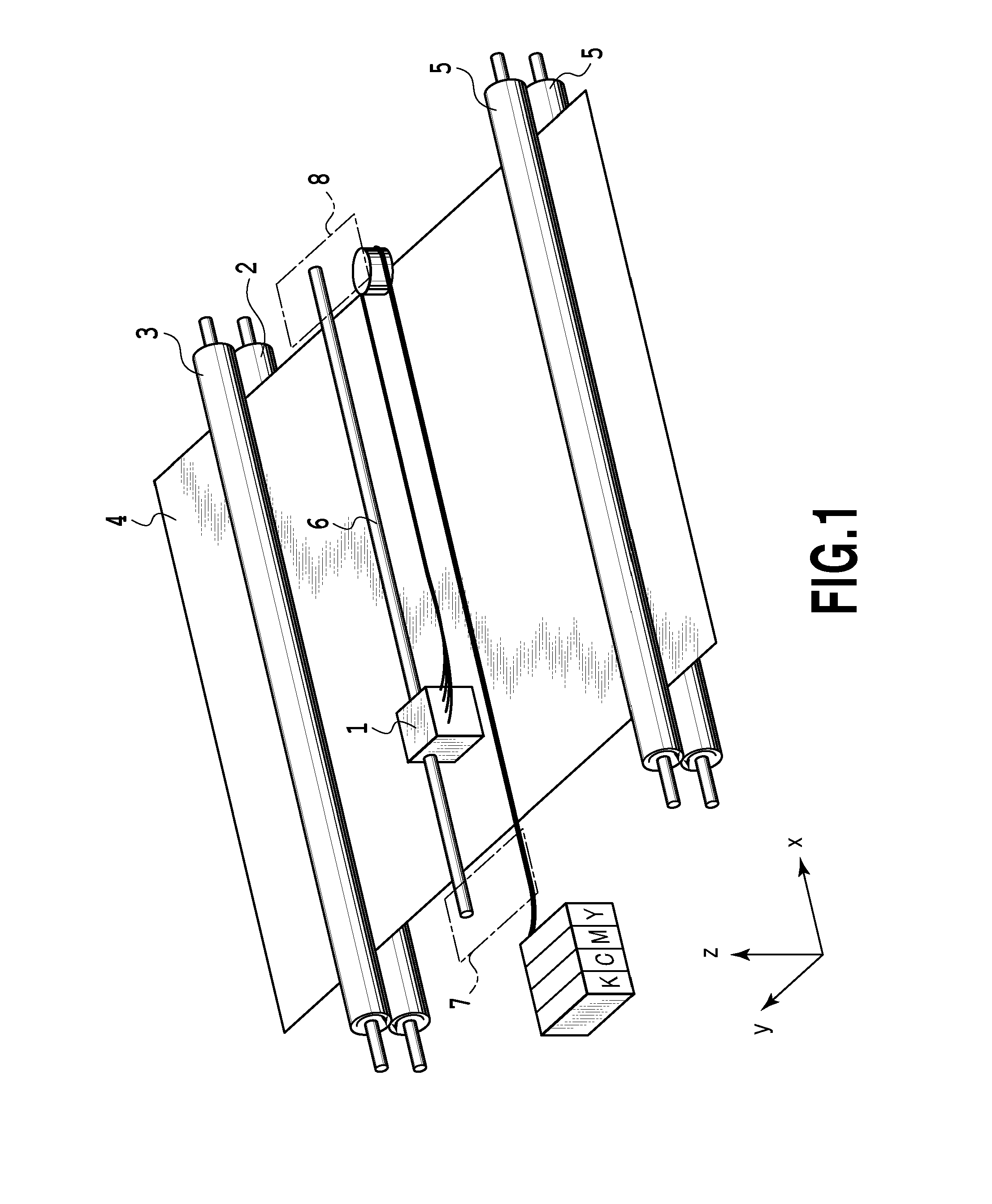
[0021]FIG. 1 is a perspective view showing a primary part of an inkjet printing apparatus according to the present embodiment. A print head 1 removably mounted on the inkjet printing apparatus is provided with ink tanks separated therefrom, and forms an image by inks supplied through tubes or the like from the ink tanks. The ink head 1 is provided with ink supply portions in accordance with kinds of inks, and is provided with individual liquid chambers therein, each of which is formed for each ink in such a manner that the inks are not blended with each other in the print head 1.
[0022]A print medium 4 that is supplied by paper conveying rollers 5 is conveyed in a y direction while being tightly sandwiched by a paper conveying roller 2 and an auxiliary roller 3 each rotating in an arrow direction shown in the figure. The pair of paper conveying rollers 5 tightly holds the print medium 4 therebetween while rotating, and as a rotation speed thereof is made smaller than that of the paper c
second embodiment
[0041]In the first embodiment, when the total ejection number from the printing start or the recovery processing reaches a constant threshold or more, the pulse width in the drive control of the preliminary ejection is made longer to suppress the non-ejection of the ink. However, the present invention is not limited to the first embodiment where when the total ejection number from the printing start or the recovery processing reaches a constant threshold or more, the pulse width in the drive control of the preliminary ejection is changed.
[0042]The drive control of the preliminary ejection in the present embodiment is configured to change a drive voltage therein when the total ejection number from the printing start or the recovery processing reaches a constant threshold or more.
[0043]The inkjet printing apparatus and the print head in the present embodiment have the same configuration as the printing apparatus and the print head in the first embodiment.
[0044]In the present embodiment,
third embodiment
[0046]The drive control of the preliminary ejection in the present embodiment is configured to change a drive frequency therein when the total ejection number from the printing start or the recovery processing reaches a constant threshold or more.
[0047]The inkjet printing apparatus and the print head in the present embodiment have the same configuration as the printing apparatus and the print head in the first embodiment.
[0048]In the present embodiment, when the total ejection number of ink droplets from the printing start is less than the total ejection number threshold X1 (X1=40 million ejections), the preliminary ejection is performed based on a condition of condition A1 shown in Table 3.
TABLE 3Table 3: a Preliminary Ejection Drive Condition in the Third EmbodimentDrive ConditionA1A2Drive Voltage24.0 V24.0 VDrive FrequencyF1f2(1 kHz)(10 kHz)Drive Time0.01 s0.01 sPulse Width0.60 μs0.60 μs
[0049]On the other hand, when the total ejection number of ink droplets is equal to or more than
PUM
 Abstract
Description
Claims
Application Information
 - R&D Engineer
- R&D Manager
- IP Professional
- Industry Leading Data Capabilities
- Powerful AI technology
- Patent DNA Extraction
Browse by: Latest US Patents, China's latest patents, Technical Efficacy Thesaurus, Application Domain, Technology Topic.
© 2024 PatSnap. All rights reserved.Legal|Privacy policy|Modern Slavery Act Transparency Statement|Sitemap