Brushless motor and electric device mounted with same
a permanent magnet, brushless motor technology, applied in the direction of dynamo-electric machines, magnetic circuit rotating parts, magnetic circuit shapes/forms/construction, etc., can solve the problems of vibration and noise, increase torque ripple, and speed of brushless motor cannot be increased any more, so as to reduce noise and vibration in a high-speed region, low noise, and low vibration operation
- Summary
- Abstract
- Description
- Claims
- Application Information
AI Technical Summary
Benefits of technology
Problems solved by technology
Method used
Image

Examples
first exemplary embodiment
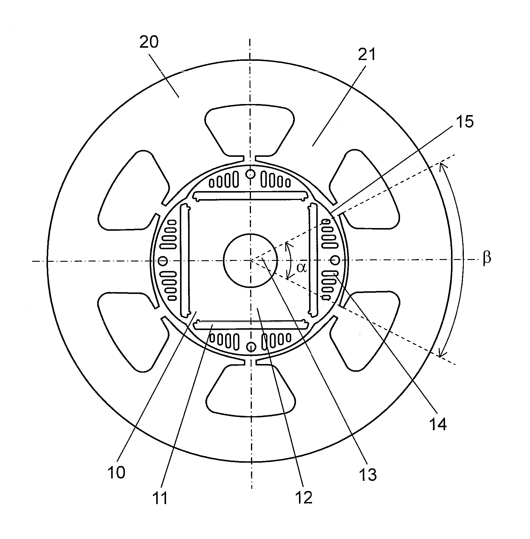
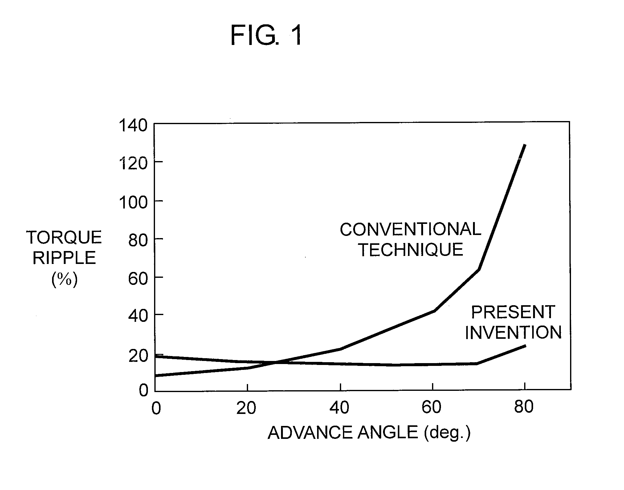
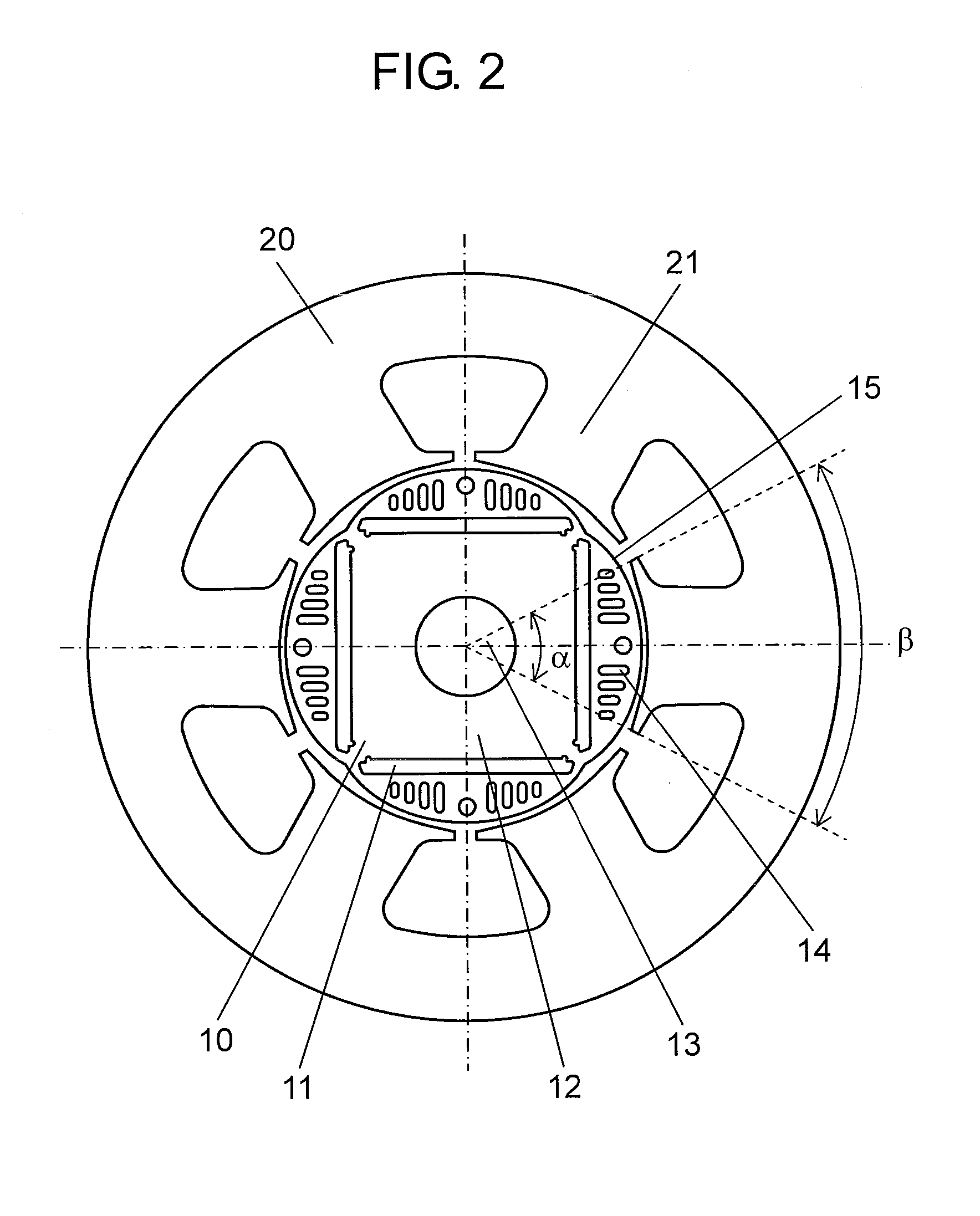
[0024]FIG. 1 is a diagram showing the relationship between current phase advance angle and torque ripple of a brushless motor according to the first exemplary embodiment of the present invention and a conventional brushless motor. FIG. 2 is a diagram showing a stator and a rotor of the brushless motor according to the first exemplary embodiment of the present invention. FIG. 3 is a diagram showing the rotor of the brushless motor according to the first exemplary embodiment of the present invention. FIG. 4 is an enlarged diagram of a stator slot portion of the permanent magnet brushless motor according to the first exemplary embodiment of the present invention.
[0025]As shown in FIG. 2 and FIG. 3, generally cylindrical rotor 10 is an interior permanent magnet rotor having permanent magnets embedded inside along a longitudinal direction. Rotor core 12 that forms rotor 10, which rotates around shaft 13 as an axis, is formed with a plurality of slits 14 that extend inward from vicinity of o
PUM
 Abstract
Description
Claims
Application Information
 - R&D Engineer
- R&D Manager
- IP Professional
- Industry Leading Data Capabilities
- Powerful AI technology
- Patent DNA Extraction
Browse by: Latest US Patents, China's latest patents, Technical Efficacy Thesaurus, Application Domain, Technology Topic.
© 2024 PatSnap. All rights reserved.Legal|Privacy policy|Modern Slavery Act Transparency Statement|Sitemap