Fast catalytic pyrolysis with recycle of side products

Active Publication Date: 2014-01-30
ANELLOTECH INC
View PDF3 Cites 34 Cited by
  • Summary
  • Abstract
  • Description
  • Claims
  • Application Information

AI Technical Summary

Benefits of technology

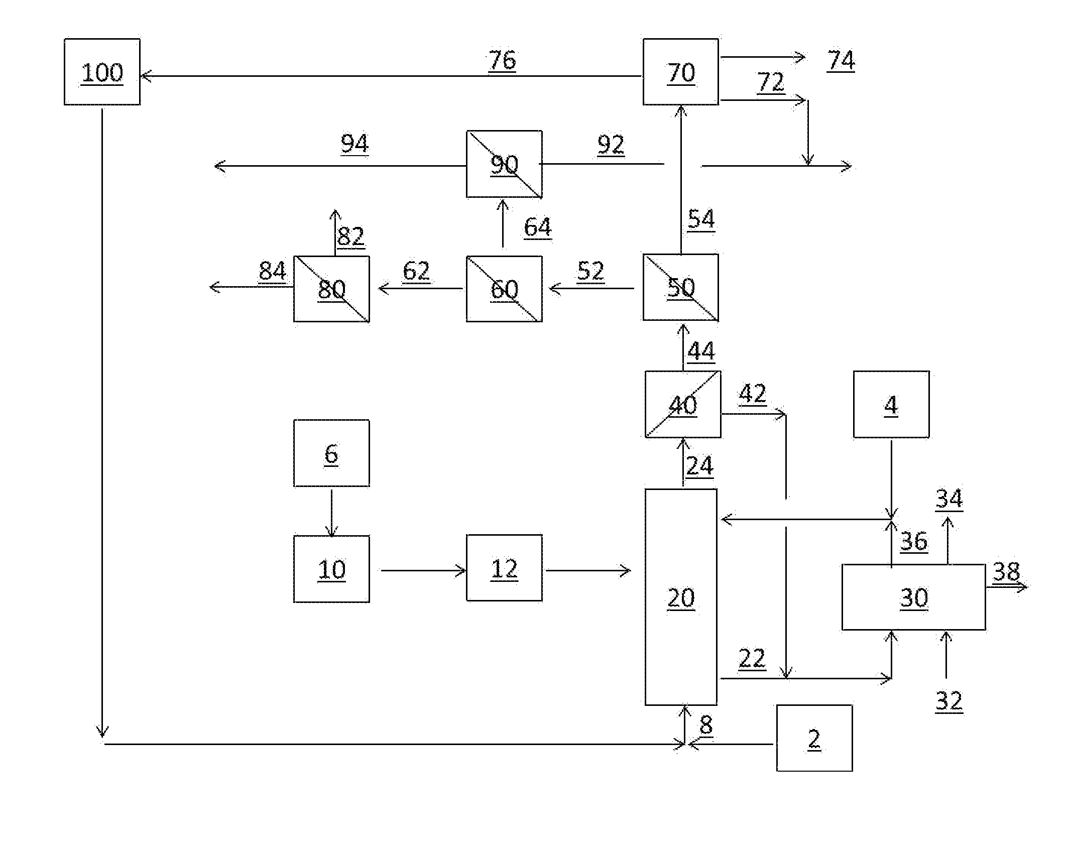
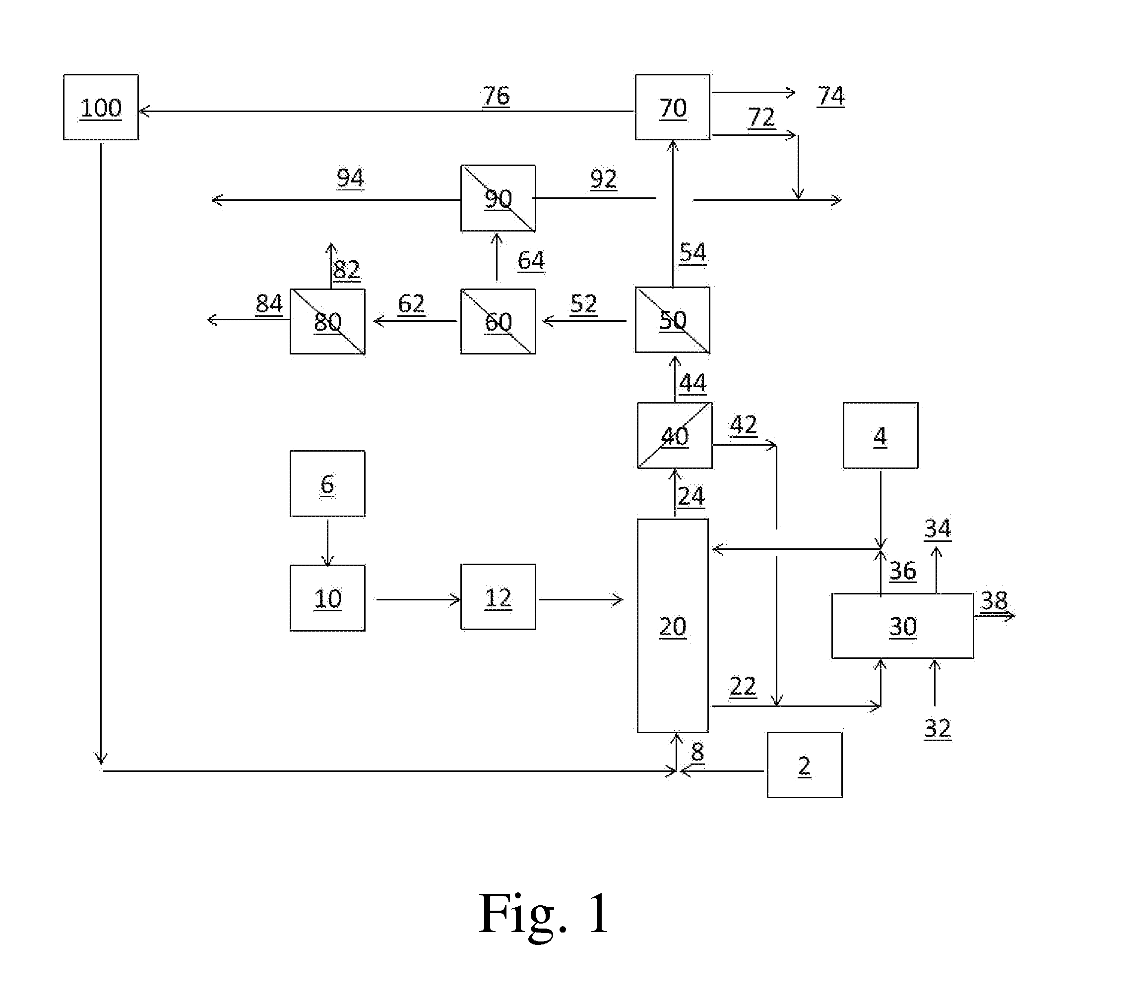
[0019]In some instances, the particle size of the feed composition may be reduced in an optional grinding system 12 prior to passing the feed to the reactor. In some embodiments, the average diameter of the ground feed composition exiting the grinding system may comprise no more than about 50%, not more than about 25%, no more than about 10%, no more than about 5%, no more than about 2% of the average diameter of the feed composition fed to the grinding system. Large-particle feed material may be more easily transportable and less difficult to process than small-particle feed material. On the other hand, in some cases it may be advantageous to feed small particles to the reactor (as discussed below). The use of a grinding system allows for the transport of large-particle feed between the source and the process, while enabling the feed of small particles to the reactor.

Problems solved by technology

However, lignocellulosic biomass is not currently commonly used as a liquid fuel or chemicals source because typical current conversion processes are not considered to be economically viable.
Unfortunately, neither the APP nor the syngas process meets such criteria.
Conventional fast pyrolysis often produces a thermally unstable, liquid product mixture, called bio-oil, an acidic, combustible liquid mixture of more than 300 compounds that degrades over time.
However, bio-oils are not compatible with existing liquid transportation fuels, such as gasoline and diesel, and their yields are low.

Method used


Image

  • Fast catalytic pyrolysis with recycle of side products
  • Fast catalytic pyrolysis with recycle of side products

Examples


Example

GLOSSARY

Aromatics

[0035]As used herein, the terms “aromatics” or “aromatic compound” are used to refer to a hydrocarbon compound or compounds comprising one or more aromatic groups such as, for example, single aromatic ring systems (e.g., benzyl, phenyl, etc.) and fused polycyclic aromatic ring systems (e.g. naphthyl, 1,2,3,4-tetrahydronaphthyl, etc.). Examples of aromatic compounds include, but are not limited to, benzene, toluene, indane, indene, 2-ethyl toluene, 3-ethyl toluene, 4-ethyl toluene, trimethyl benzene (e.g., 1,3,5-trimethyl benzene, 1,2,4-trimethyl benzene, 1,2,3-trimethyl benzene, etc.), ethylbenzene, styrene, cumene, methylbenzene, propylbenzene, xylenes (e.g., p-xylene, m-xylene, o-xylene, etc.), naphthalene, methyl-naphthalene (e.g., 1-methyl naphthalene, anthracene, 9,10-dimethylanthracene, pyrene, phenanthrene, dimethyl-naphthalene (e.g., 1,5-dimethylnaphthalene, 1,6-dimethylnaphthalene, 2,5-dimethylnaphthalene, etc.), ethyl-naphthalene, hydrindene, methyl-hydrinden


PUM


Abstract

This invention relates to improvements in the fast pyrolysis of biomass. In this invention, a portion of the products from a pyrolysis reactor are condensed in the liquid phase and at least a portion of the recovered liquid is recycled to the pyrolysis reactor for further conversion to valuable, useful products.

Description


Claims


Application Information

Patent Timeline
Owner ANELLOTECH INC
Why Eureka
Try Eureka