Anode device and maintenance method

a technology of anode and maintenance method, which is applied in the field of anode device and maintenance method, can solve the problems of seawater escape from the cooling system, contaminating or corroding other nearby components, and difficult withdrawal of brass fittings containing zinc from the port, so as to facilitate the installation and replacement of anodes, minimize or prevent the escape of fluid, and minimize the effect of seawater escap

Inactive Publication Date: 2014-03-13
MCMULLEN ALAN
View PDF6 Cites 4 Cited by
  • Summary
  • Abstract
  • Description
  • Claims
  • Application Information

AI Technical Summary

Benefits of technology

The technical effect of this patented invention is to create a better way to install and remove anodes used in marine engines, while also reducing the risk of leakage of sea water into the cooling system. Additionally, it provides a solution where the anode can be easily removed without having to change any parts.

Problems solved by technology

The technical problem addressed by this patent is how to prevent corrosive damage caused by sea water during the operation of marine engines while maintaining their functionality.

Method used


Image

  • Anode device and maintenance method
  • Anode device and maintenance method
  • Anode device and maintenance method

Examples


Embodiment Construction

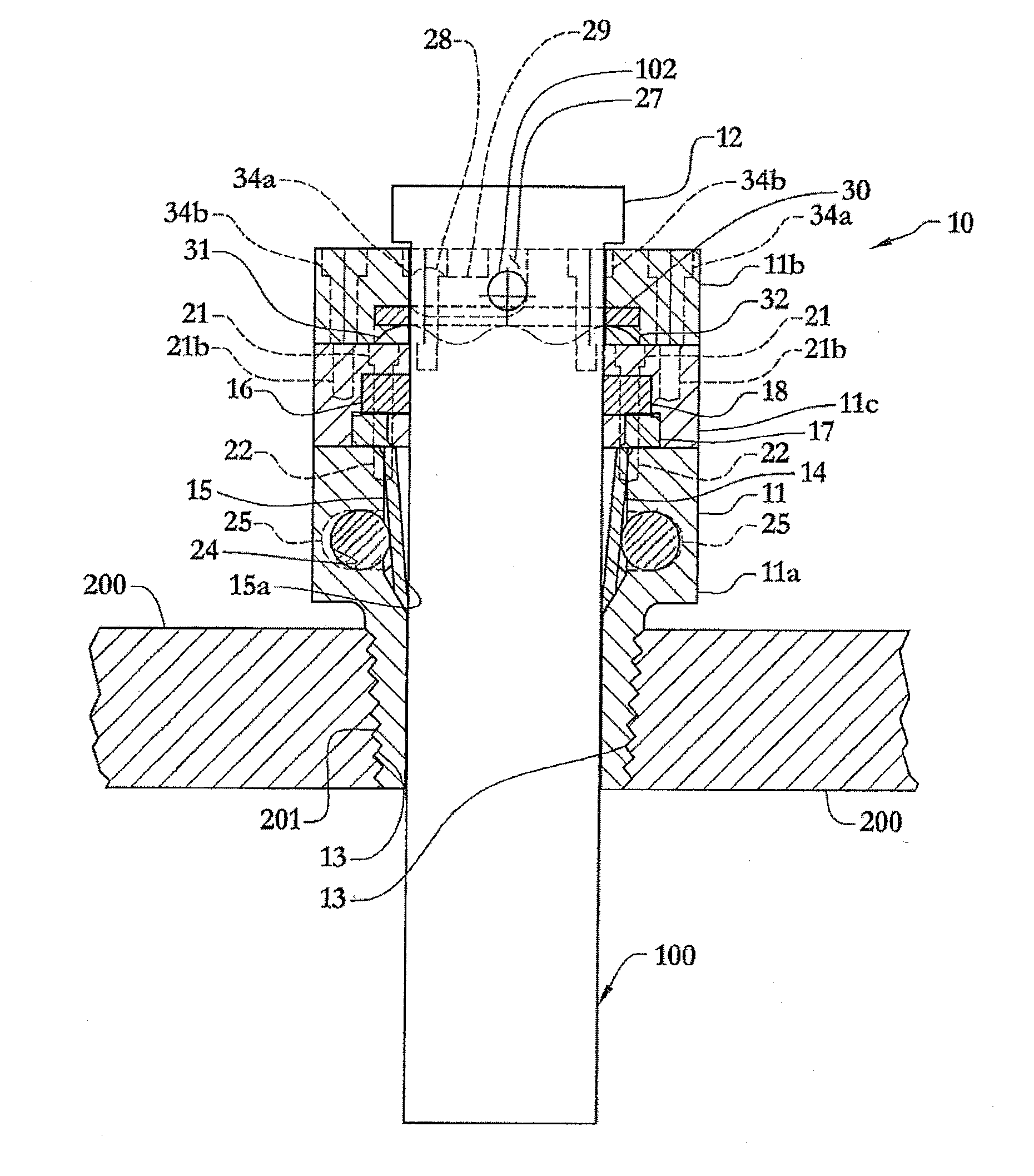
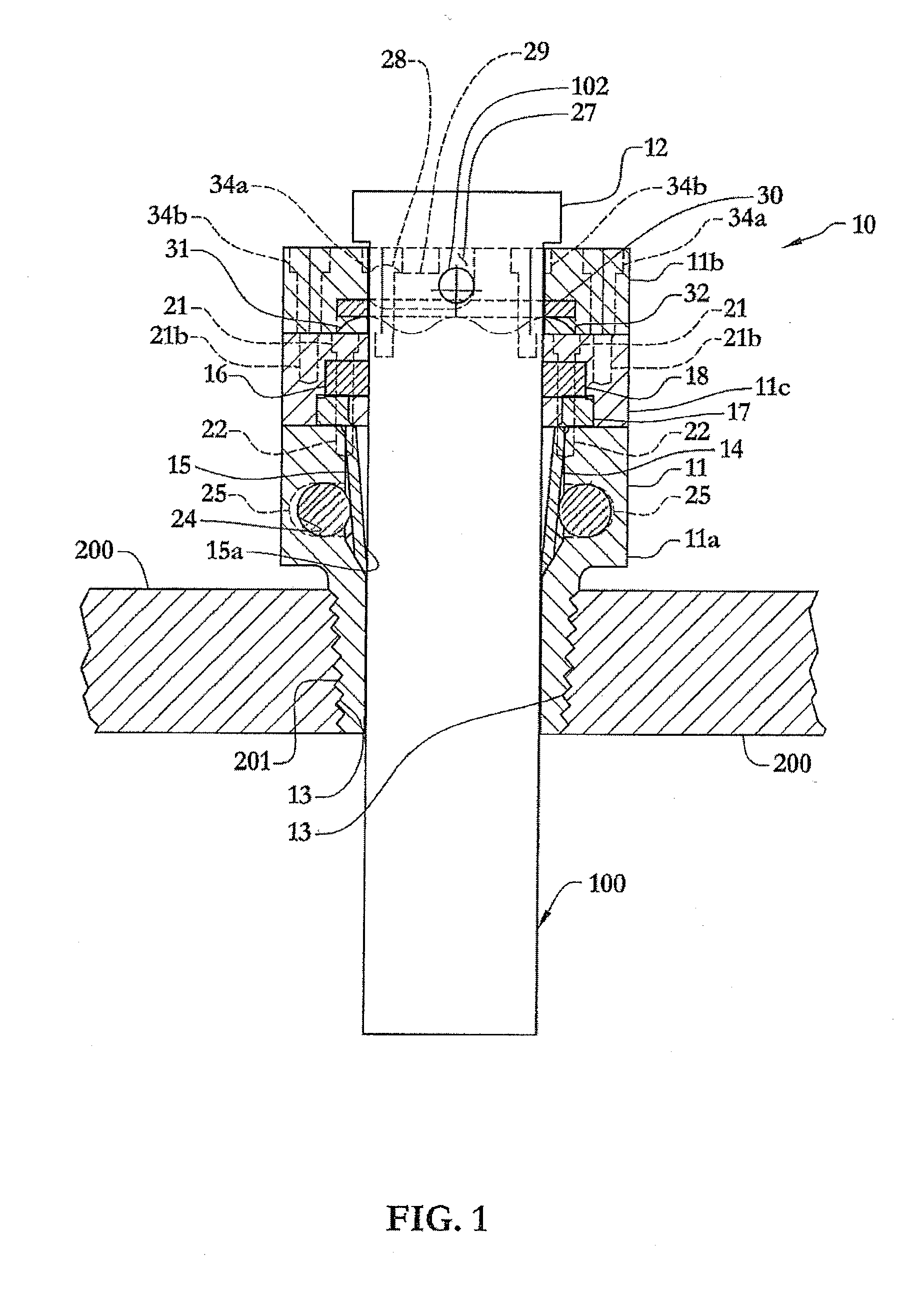
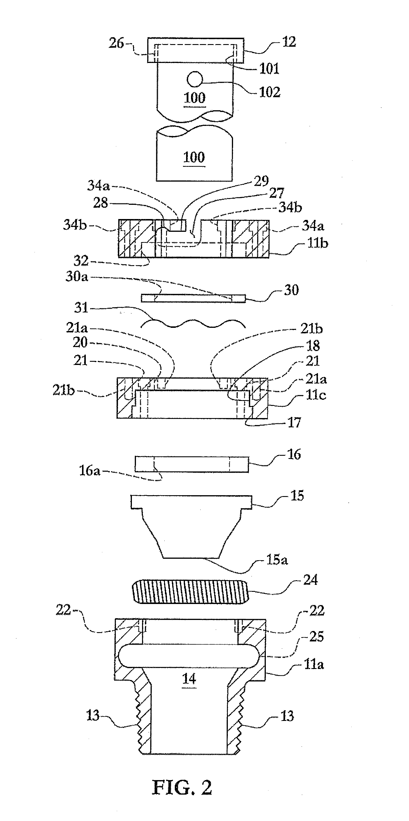
[0034]Referring to FIG. 1, a preferred embodiment of an anode plug device 10 is shown with an anode 100 held therein. The anode plug device 10 is shown according to a preferred embodiment having a connector 11 that has a channel therethrough. According to a preferred embodiment, the connector 11 is illustrated having a lower body portion 11a, an upper body portion 11b, and a connecting portion lie. The connector 11 preferably has a threaded portion 13 that is matingly threaded for connection to a threaded bore 201 of an engine cooling system component, such as the pipe 200 (or other structure to which the device 10 is mounted). The connector 11 preferably has sealing means comprising a sealing mechanism for sealing the passage of seawater from escaping through the connector 10 when the anode 100 is removed. The sealing mechanism preferably comprises a sealing component. According to some embodiments, the sealing component may comprise a spring-loaded wafer valve. According to other emb


PUM


Abstract

A method and device for facilitating maintenance of an anode of a marine engine cooling system, the device including an anode for use with an anode plug such as, for example, an anode plug that has a detachable component with a threaded end for mounting to a threaded bore of a cooling system structure, and a connector that holds the anode, the anode having an indicator for indicating a condition of the anode which is indicative of a need to replace the anode The method permits changing the anode by removing and/or reinstalling an anode while preventing or minimizing water from exiting the cooling system of the marine engine.

Description


Claims


Application Information

Patent Timeline
Owner MCMULLEN ALAN
Why Eureka
Try Eureka