Method and apparatus for determining differential flow characteristics of a multiple meter fluid flow system

Active Publication Date: 2014-05-08
MICRO MOTION INC
View PDF0 Cites 11 Cited by
  • Summary
  • Abstract
  • Description
  • Claims
  • Application Information

AI Technical Summary

Benefits of technology

[0009]A fluid flow system is provided according to an embodiment. The fluid flow system includes a pipeline with a flowing fluid and a first vibrating meter including a first sensor assembly located within the pipeline and configured to determine one or more flow characteristics, including a first flow rate. According to an embodiment, the fluid flow system further includes a second vibrating meter including a second sensor assembly located within the pipeline and in fluid communication with the first sensor assembly and configured to determine one or more flow characteristics, including a seco

Problems solved by technology

Although this initially determined zero offset can adequately correct the measurements in limited circumstances, the zero offset may change over time due to a change in a variety of operating conditi

Method used


Image

  • Method and apparatus for determining differential flow characteristics of a multiple meter fluid flow system
  • Method and apparatus for determining differential flow characteristics of a multiple meter fluid flow system
  • Method and apparatus for determining differential flow characteristics of a multiple meter fluid flow system

Examples


Embodiment Construction

[0056]FIGS. 1-7 and the following description depict specific examples to teach those skilled in the art how to make and use the best mode of embodiments of a vibrating meter system. For the purpose of teaching inventive principles, some conventional aspects have been simplified or omitted. Those skilled in the art will appreciate variations from these examples that fall within the scope of the present description. Those skilled in the art will appreciate that the features described below can be combined in various ways to form multiple variations of the vibrating meter system. As a result, the embodiments described below are not limited to the specific examples described below, but only by the claims and their equivalents.

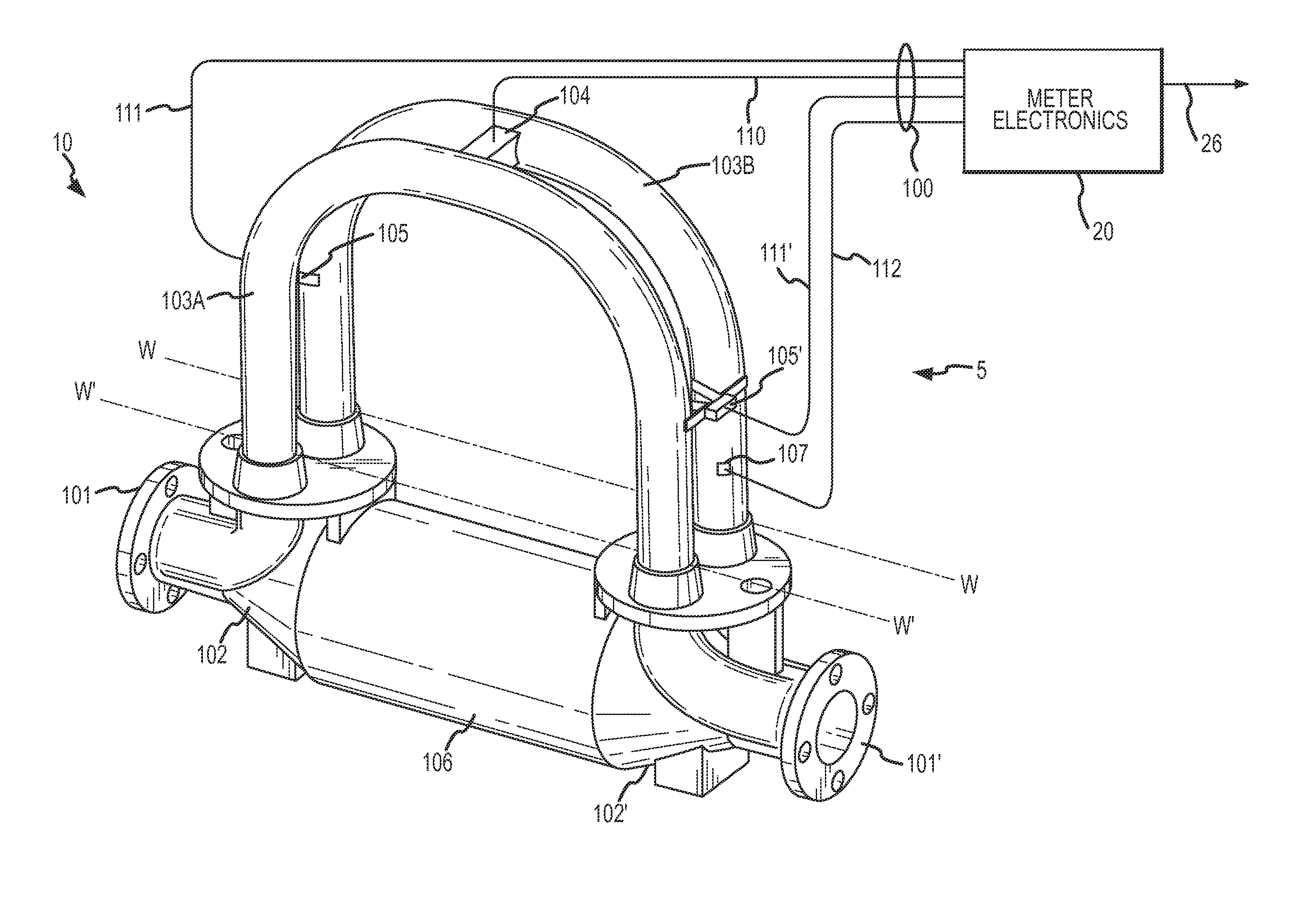
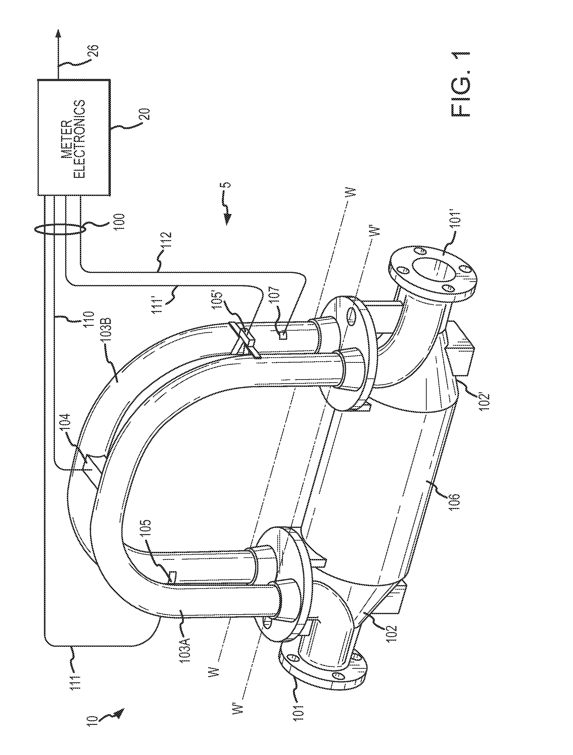
[0057]FIG. 1 shows an example of a vibrating meter 5 in the form of a Coriolis flow meter comprising a sensor assembly 10 and one or more meter electronics 20. The meter electronics 20 is connected to the sensor assembly 10 via leads 100 to measure one or more flow c


PUM


Abstract

A fluid flow system (300) is provided. The fluid flow system (300) includes a pipeline (302) with a flowing fluid. The fluid flow system (300) further includes a first vibrating meter (5) including a first sensor assembly (10) located within the pipeline (302) and configured to determine one or more flow characteristics, including a first flow rate. A second vibrating meter (5′) including a second sensor assembly (10′) located within the pipeline (302) is provided that is in fluid communication with the first sensor assembly (10) and configured to determine one or more flow characteristics, including a second flow rate. The fluid flow system (300) further includes a system controller (310) in electrical communication with the first and second vibrating meters (5, 5′). The system controller (310) is configured to receive the first and second flow rates and determine a differential flow rate based on the first and second flow rates. The system controller (310) is further configured to compare the differential flow rate to a threshold value or band and correct one or more flow characteristics if the differential flow rate is less than a threshold value or band.

Description


Claims


Application Information

Patent Timeline
Owner MICRO MOTION INC
Why Eureka
Try Eureka