Intake Module for an Internal Combustion Engine

Active Publication Date: 2014-09-04
DAIMLER AG
View PDF9 Cites 4 Cited by
  • Summary
  • Abstract
  • Description
  • Claims
  • Application Information

AI Technical Summary

Benefits of technology

[0015]In one advantageous embodiment of the invention, a first connecting flange surface of the air duct element, via which the air duct element is to be connected to the cylinder head, and a second connecting flange surface of the cylinder head cover, via which the cylinder head cover is to be connected to the cylinder head, are situated at least essentially in a shared plane. In this way, the intake module according to the invention may be installed in a particularly simple manner, and produced in a time-saving and thus cost-effective manner. Correspondingly, a third connecting flange surface corresponding to the first connecting flange surface as well as a fourth connecting flange surface of the cylinder head corresponding to the second connecting flange surface are likewise at least essentially situated in a shared plane. The intake module may thus be installed on the cylinder head without complicated adapter elements. Particularly simple installation of the intake module according to the invention is provided in such a cylinder head in which the third connecting flange surface is integrated into the fourth connecting flange surface (or vice versa).
[0016]In another advantageous embodiment, the air duct element includes an air distributor by means of which the air may be distributed over a plurality of combustion chambers, in particular cylinders, of the internal combustion engine. The air distributor has a collection chamber, for example, in which, for example, the air which is compressed and to be supplied to the internal combustion engine is initially collected. A plurality of air channels corresponding to the combustion chambers and into which, for example, the compressed air from the collection chamber may flow, and from which the air may flow into the combustion chambers, branches off from the collection chamber. This provides a particularly high level of functional integration of the intake module.
[0017]It has also

Problems solved by technology

This large number of components requires a complicated assembly, resulting in time-consuming and costly assembly of the overall internal combustion engine.
It is thus apparent that additional time-consuming and costly installation steps for separately installing the lubricant separation device, the cylinder head cover, a

Method used


Image

  • Intake Module for an Internal Combustion Engine
  • Intake Module for an Internal Combustion Engine

Examples


Example

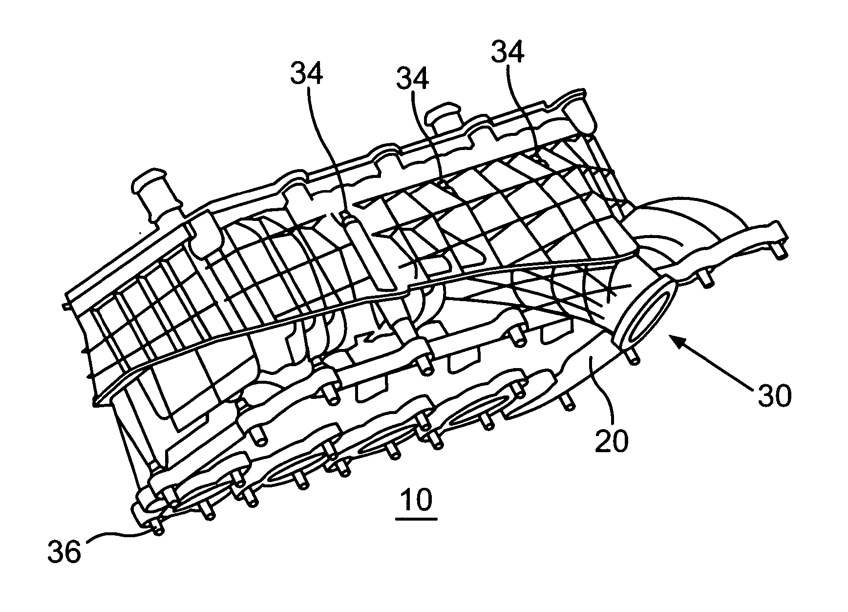
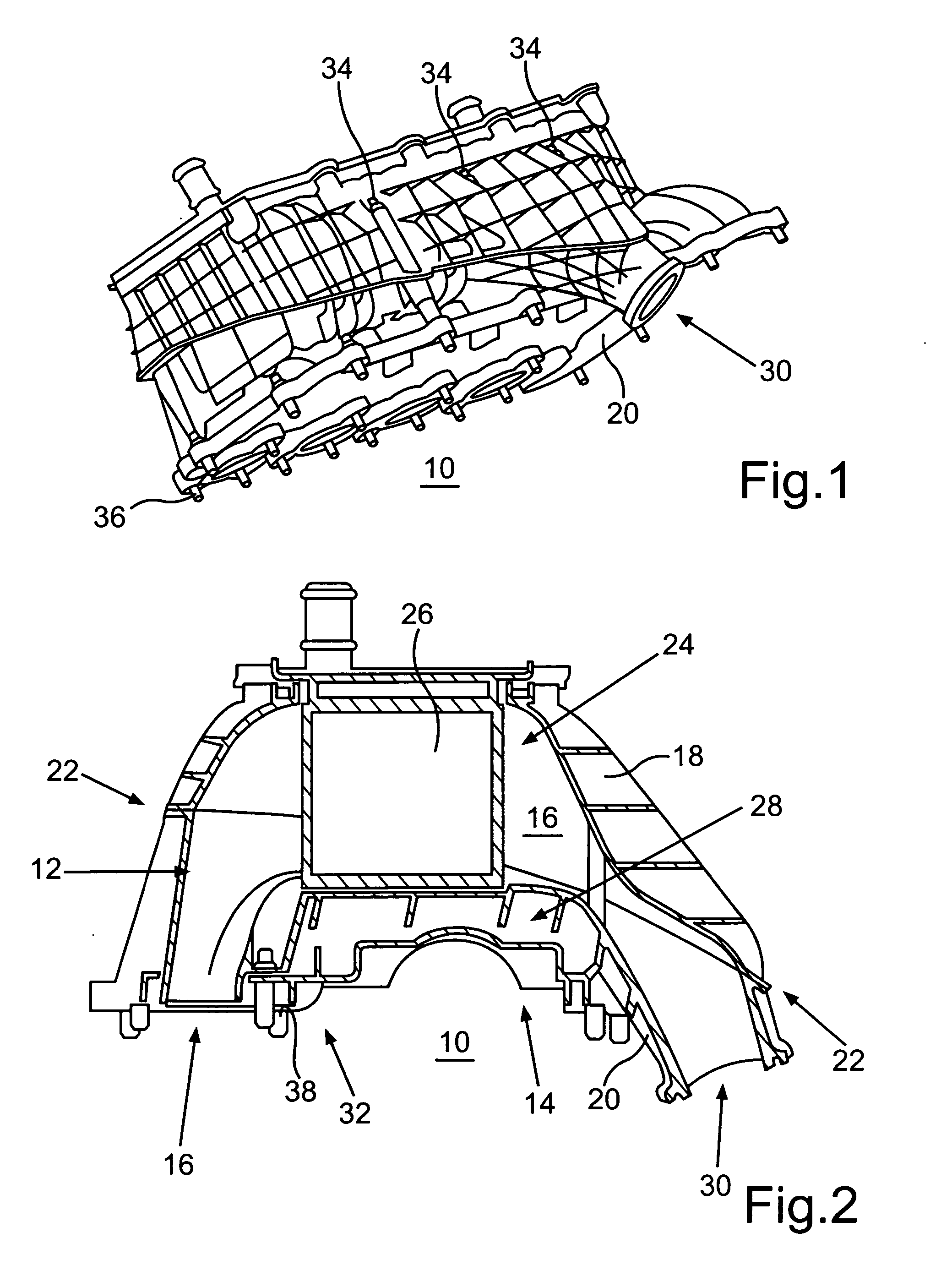
[0026]FIG. 1 shows an intake module 10 for an internal combustion engine designed as a reciprocating piston internal combustion engine of a motor vehicle, in particular a passenger vehicle. As is apparent in conjunction with FIG. 2, the intake module 10 includes an air duct element 12 by means of which air is to be supplied to the internal combustion engine. The air duct element 12 is therefore also referred to as an intake manifold, since the internal combustion engine may draw in air via the air duct element.

[0027]The intake module 10 also includes a cylinder head cover 14 by means of which a cylinder head of the internal combustion engine is to be at least partially covered, and which is designed in one piece with the air duct element 12. Associated with the air duct element 12 are air channels 16 via which the air is able to flow into cylinders of the internal combustion engine, and which are partially delimited on the one hand by an upper housing part 18 of the intake module 10 an


PUM


Abstract

An intake module an internal combustion engine of a motor vehicle includes at least one air duct element via which air is to be supplied to the internal combustion engine, and a cylinder head cover connected to the air duct element by means of which a cylinder head of the internal combustion engine is to be at least partially covered. A lubricant separation device and a cooling device for cooling the air are integrated into the intake module.

Description


Claims


Application Information

Patent Timeline
Owner DAIMLER AG
Why Eureka
Try Eureka