Chassis for Rail Vehicles

Active Publication Date: 2020-02-27
SIEMENS MOBILITY AUSTRIA GMBH
View PDF0 Cites 2 Cited by
  • Summary
  • Abstract
  • Description
  • Claims
  • Application Information

AI Technical Summary

Benefits of technology

[0013]Actuating forces acting on the first wheel are transferred from the actuator unit and via the lever to the wheel bearing housing. In this context, the lever brings about a favorable force transmission, whereby the actuator unit can be dimensioned in a compact manner.
[0014]An advantageous solution is obtained when the actuator unit has at least one pneumatic actuator. This achieves the advantage that a compressed air system provided in the rail vehicle, e.g., for a pneumatic brake system, can also be used to supply the actuator unit, leaks in the actuator unit do not lead to any environmental pollution and the actuator unit can be separated from the compressed air system in a simple manner for maintenance purposes and connected to it once again.

Problems solved by technology

Depending on the mounting of the components on the chassis, this may lead to high unsprung masses and to a heavy loading of track bodies and on the components of the wheel controller or wheelset controller itself.
High unsprung masses of a vehicle, and a heavy loading of a track body may, for instance, lead to high route usage fees (e.g., Track Access Charges in the United Kingdom), which must be paid by a vehicle operator.
The approaches mentioned, in their known forms, have the disadvantage that components of the wheelset guiding or wheelset actuating facilities are partially mounted on wheelset bearings and unsprung masses of the chassis increase as a result.

Method used


Image

  • Chassis for Rail Vehicles

Examples


Example

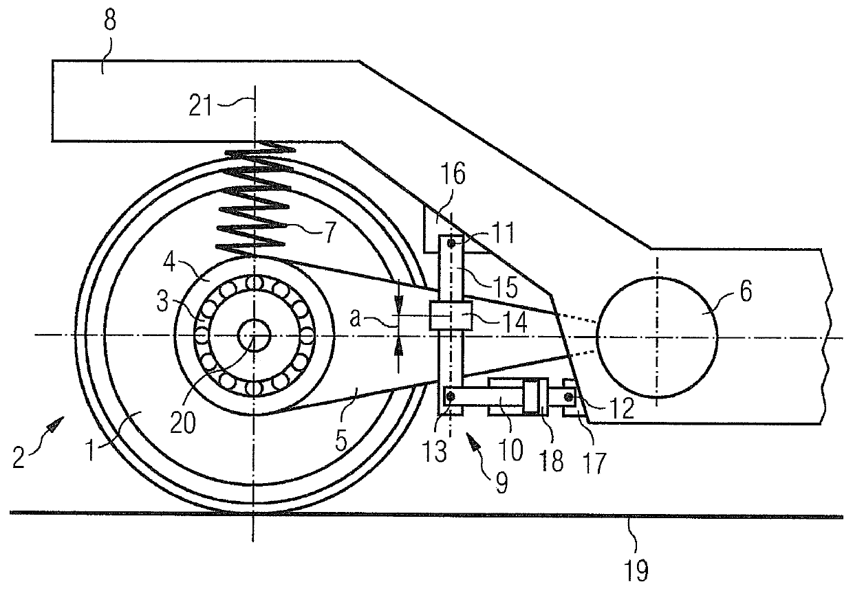
[0018]A detail, shown in a side view in the FIGURE, of an exemplary embodiment of a chassis in accordance with the invention of a rail vehicle comprises a detail of a support structure 8 as well as a first wheel 1, which lies against a track 19.

[0019]The support structure 8 is formed as a chassis frame with sole bars and a cross member. In accordance with the invention, with regard to geometry, connection technology, or materials, different embodiments of support structures 8 are conceivable.

[0020]The support structure 8 may be formed / structured as one part or as multiple parts. In multipart embodiments, it is possible, for instance, to interconnect individual parts in an articulated manner, etc.

[0021]The first wheel 1 is arranged around a crossarm 20 and connected to a first wheelset shaft (not shown) which extends along the crossarm 20. Arranged on the first wheelset shaft is a first wheel bearing 3, which is shrouded by a first wheel bearing housing 4.

[0022]The first wheel bearing


PUM


Abstract

A chassis for rail vehicles includes at least one first wheel and one second wheel, at least one first wheel bearing having a first wheel bearing housing and a second wheel bearing having a second wheel bearing housing, at least one first primary spring and one second primary spring, at least one primary spring-loaded support structure and at least one active wheel positioning device, which has an actuator unit, where a first bearing and a second bearing are provided between the at least one wheel positioning device and the at least one support structure, and a guide is provided between the at least one wheel positioning device and the first wheel bearing housing, and where the unsuspended mass of the chassis is reduced by the suspension of the wheel positioning device on the primary spring-loaded support structure in order to create advantageous design conditions.

Description


Claims


Application Information

Patent Timeline
Owner SIEMENS MOBILITY AUSTRIA GMBH
Why Eureka
Try Eureka