Drive Circuit For Electrical Load

a technology of driving circuit and load, which is applied in the direction of ac-dc conversion, electrical apparatus, energy industry, etc., can solve the problems of significant cost implications, distorted current generation of igbts, and the conventional transformer used to feed a rectifier comprising diode bridges will not improve the distorted current generated, etc., to achieve cost-effective implementation, low total harmonic distortion, and the effect of improving efficiency

Inactive Publication Date: 2014-09-04
NIDEC CONTROL TECHN LTD
View PDF4 Cites 3 Cited by
  • Summary
  • Abstract
  • Description
  • Claims
  • Application Information

AI Technical Summary

Benefits of technology

The technical effect of this patented technology is that it can achieve very low levels of total harmonics distortion while being cost-effective and efficient for use.

Problems solved by technology

The technical problem addressed in this patent is how to reduce the amount of energy lost during power conversion while maintaining good efficiency. Harmonics can interfere with the operation of electronic equipment or degrade their performance. To address these issues, various techniques like adding filters and reducing impedance are discussed.

Method used


Image

  • Drive Circuit For Electrical Load
  • Drive Circuit For Electrical Load
  • Drive Circuit For Electrical Load

Examples


Embodiment Construction

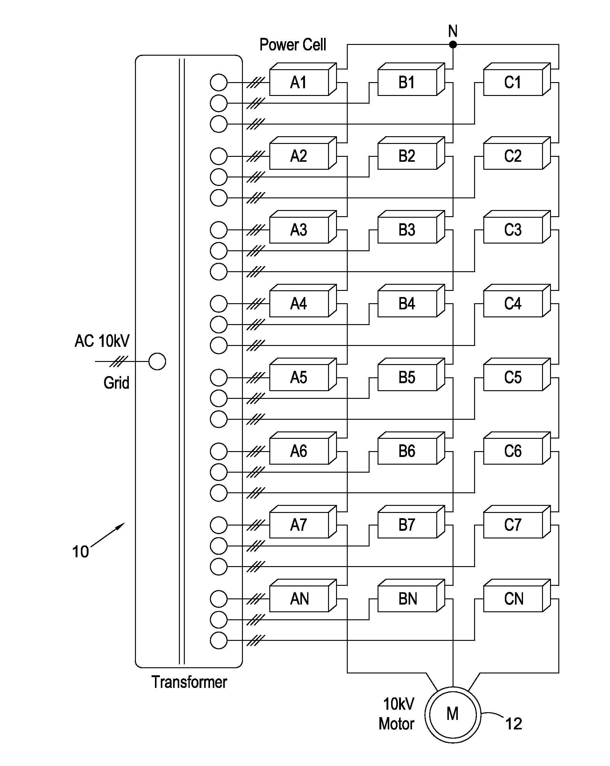
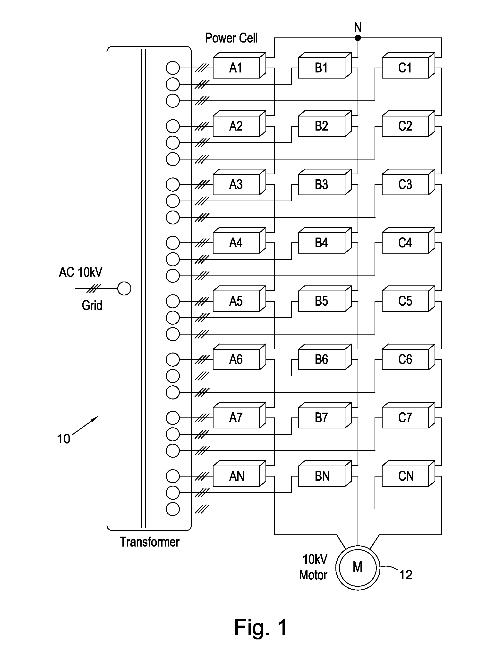
[0016]Referring to FIG. 1, a drive of a three phase motor comprises a non-phase shifting transformer 10 having a secondary with outputs at various tappings A-N corresponding to the voltage ratios required. The output of the tappings are each three phase voltages supplied to power cells A1, B1, C1-AN, BN, CN. The power cells provide the supply voltages A, B and C to the electrical load 12 which may be, for example, a 10 kV 3-phase induction motor as illustrated. Any other suitable AC electrical load can be driven by the same drive circuit. In the following the rating of the circuit components is assumed to be suitable for the power handling capability of the circuit and the application to which it is put. For example, some of the switches are power switching devices and the accompanying components have power handling characteristics as appropriate.

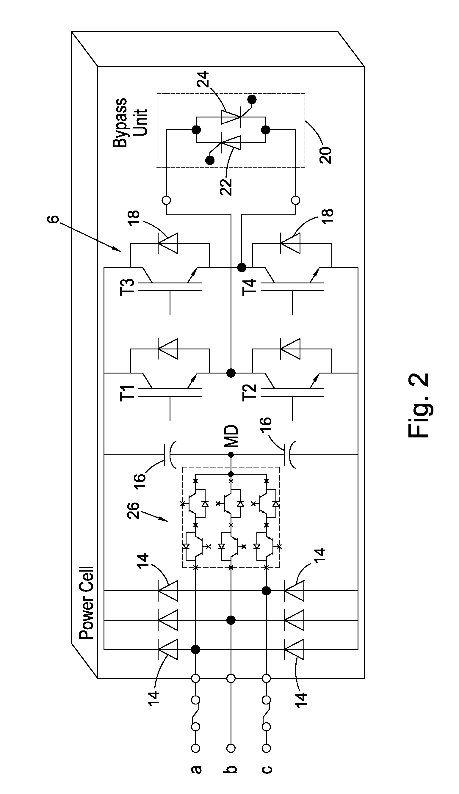
[0017]FIG. 2 illustrates the circuit of each power cell depicted in FIG. 1. It comprises phase inputs a, b and c corresponding to the outputs


PUM


Abstract

A circuit for an electrical load comprises a passive transformer, the secondary of which is connected to power cells for each phase according to the transformer tappings. Each power cell comprises a low cost but efficient power factor correction circuit to produce lower harmonics on the transformer.

Description


Claims


Application Information

Patent Timeline
Owner NIDEC CONTROL TECHN LTD
Why Eureka
Try Eureka