Led Assembly Having A Refractor That Provides Improved Light Control

Active Publication Date: 2014-09-18
ABL IP HLDG
View PDF11 Cites 9 Cited by
  • Summary
  • Abstract
  • Description
  • Claims
  • Application Information

AI Technical Summary

Benefits of technology

[0003]Embodiments of the invention include an LED assembly that includes optics and optical arrangements for light emitting diodes (LEDs). In some embodiments, a reflector is provided within a void between the lens and the LED. This reflector can reflect light emitted by the LED in a non-preferred direction back toward the preferred direction. In other embodiments, an optical element is formed or otherwise provided in the lens cavi

Problems solved by technology

LEDs, however, can be expensive in lumens per dollar compared to light sources.
In direction lighting applications, such as street lighting, it is ineffi

Method used


Image

  • Led Assembly Having A Refractor That Provides Improved Light Control
  • Led Assembly Having A Refractor That Provides Improved Light Control
  • Led Assembly Having A Refractor That Provides Improved Light Control

Examples


Embodiment Construction

[0017]The subject matter of embodiments of the present invention is described here with specificity to meet statutory requirements, but this description is not necessarily intended to limit the scope of the claims. The claimed subject matter may be embodied in other ways, may include different elements or steps, and may be used in conjunction with other existing or future technologies. This description should not be interpreted as implying any particular order or arrangement among or between various steps or elements except when the order of individual steps or arrangement of elements is explicitly described.

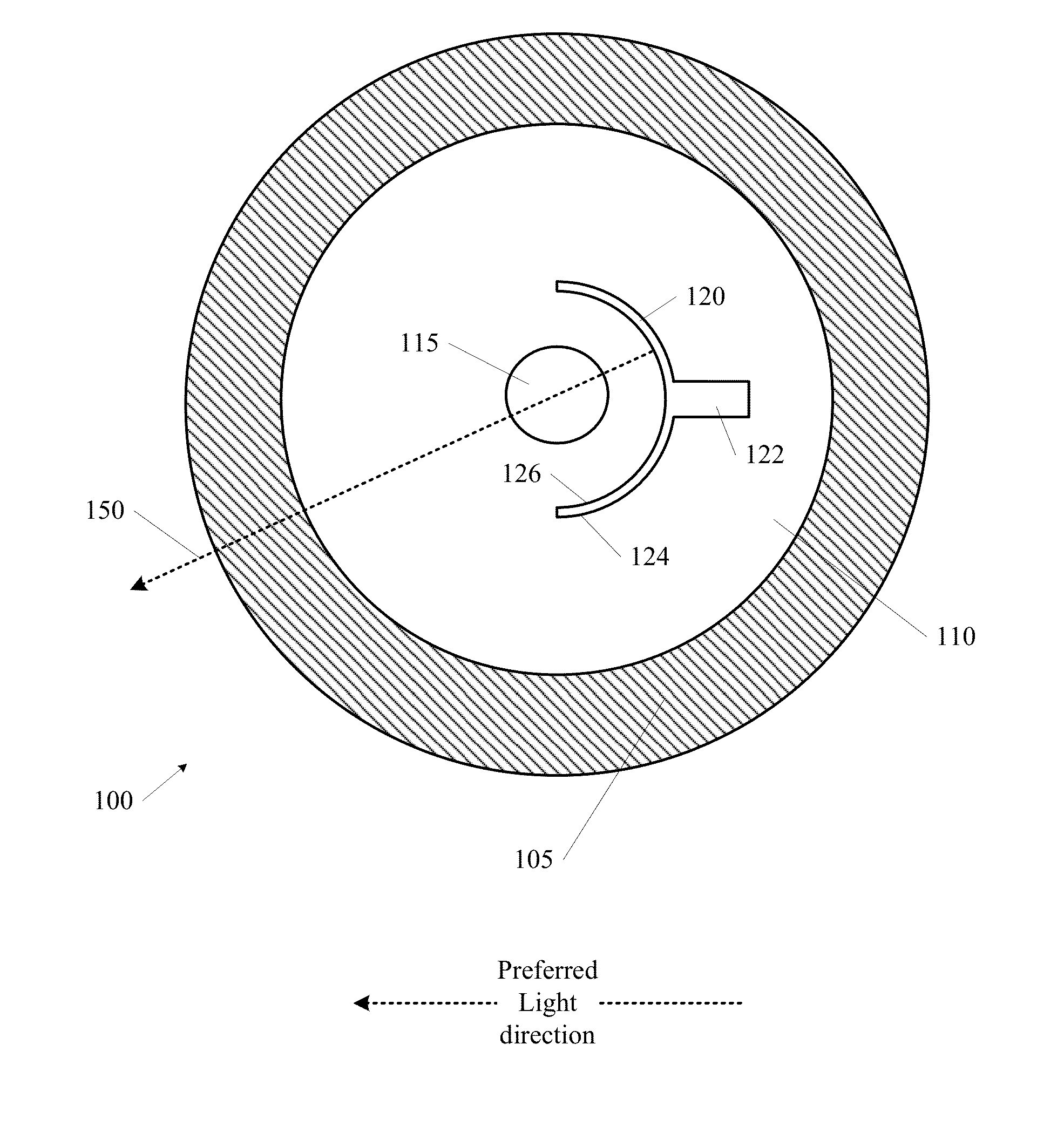
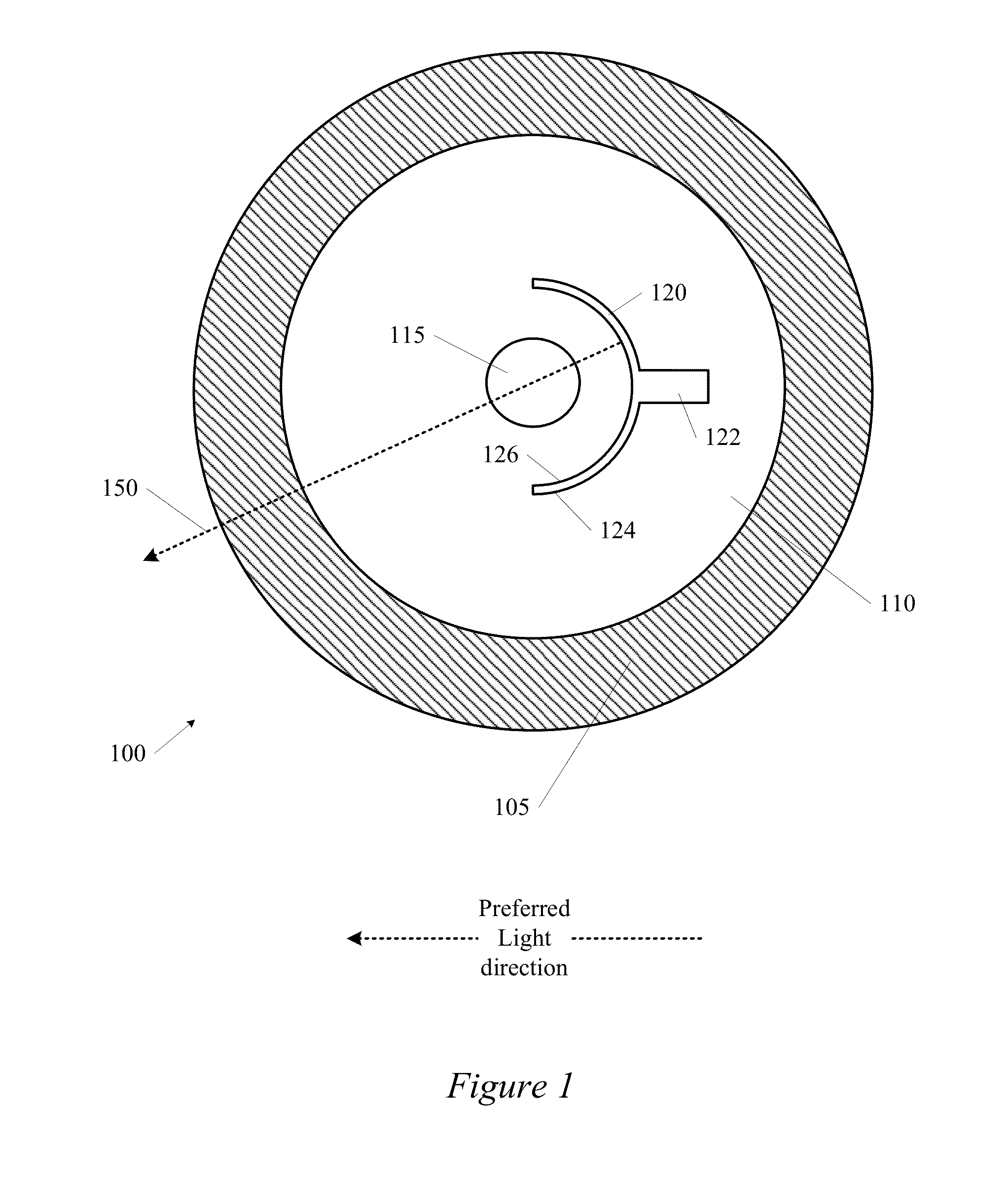
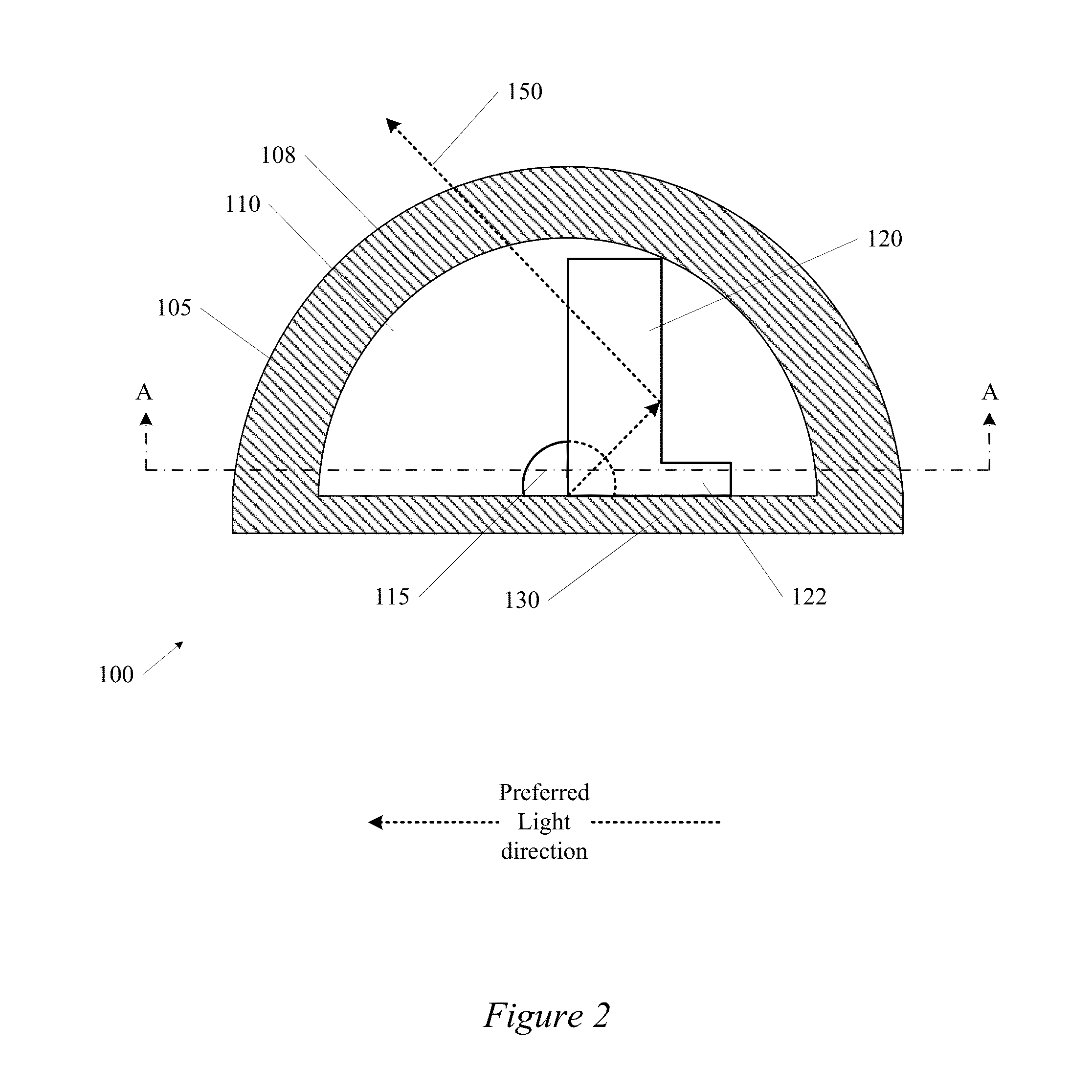
[0018]Embodiments of the invention include an LED assembly that includes optics and optical arrangements for light emitting diodes (LEDs). In some embodiments, a reflector is provided within a void between the lens and the LED. This reflector can reflect light emitted by the LED in a non-preferred direction back toward the preferred direction. In other embodiments, an optical eleme


PUM


Abstract

An LED assembly that includes optics and optical arrangements for light emitting diodes (LEDs). In some embodiments, a reflector is provided within a void between the lens and the LED. This reflector can reflect light emitted by the LED in a non-preferred direction back toward the preferred direction. In other embodiments, an optical element is formed or otherwise provided in the lens cavity and shaped so that, when the lens is positioned above the LED, the refractor bends the emitted light in a preferred direction. In some embodiments, both a reflector and optical element are provided in the LED assembly to control the directionality of the emitted light. Such embodiments of the invention can be used to increase the efficiency of an LED by ensuring that generated light is being directed to the target area of choice.

Description


Claims


Application Information

Patent Timeline
Owner ABL IP HLDG
Why Eureka
Try Eureka