Method and apparatus for generating a reference signal for a fractional-n frequency synthesizer

a fractional-n frequency synthesizer and reference signal technology, applied in the field of frequency synthesizers, can solve the problem of large timing error, achieve the effect of reducing the noise of the synthesizer output phase, facilitating the optimization of the synthesizer loop bandwidth, and facilitating the settling

Active Publication Date: 2014-11-20
QUALCOMM INC
View PDF4 Cites 18 Cited by
  • Summary
  • Abstract
  • Description
  • Claims
  • Application Information

AI Technical Summary

Benefits of technology

The patent describes a way to make it easier to generate a stable clock signal from a frequency synthesis system. This can help reduce errors caused by unwanted signals like spurious electrical activity on electronic devices. It also helps improve the performance of the frequency synthesis system.

Problems solved by technology

This patent describes how Frequency Syntheticers can generate very accurate clock signals from low frequency references. However, they also produce unwanted noise caused by imperfections in their components like filters, charge pumps, loops, and analog circuits. These issues affect the quality of the clock signals produced and degrade the overall performance of the device.

Method used


Image

  • Method and apparatus for generating a reference signal for a fractional-n frequency synthesizer
  • Method and apparatus for generating a reference signal for a fractional-n frequency synthesizer
  • Method and apparatus for generating a reference signal for a fractional-n frequency synthesizer

Examples


Embodiment Construction

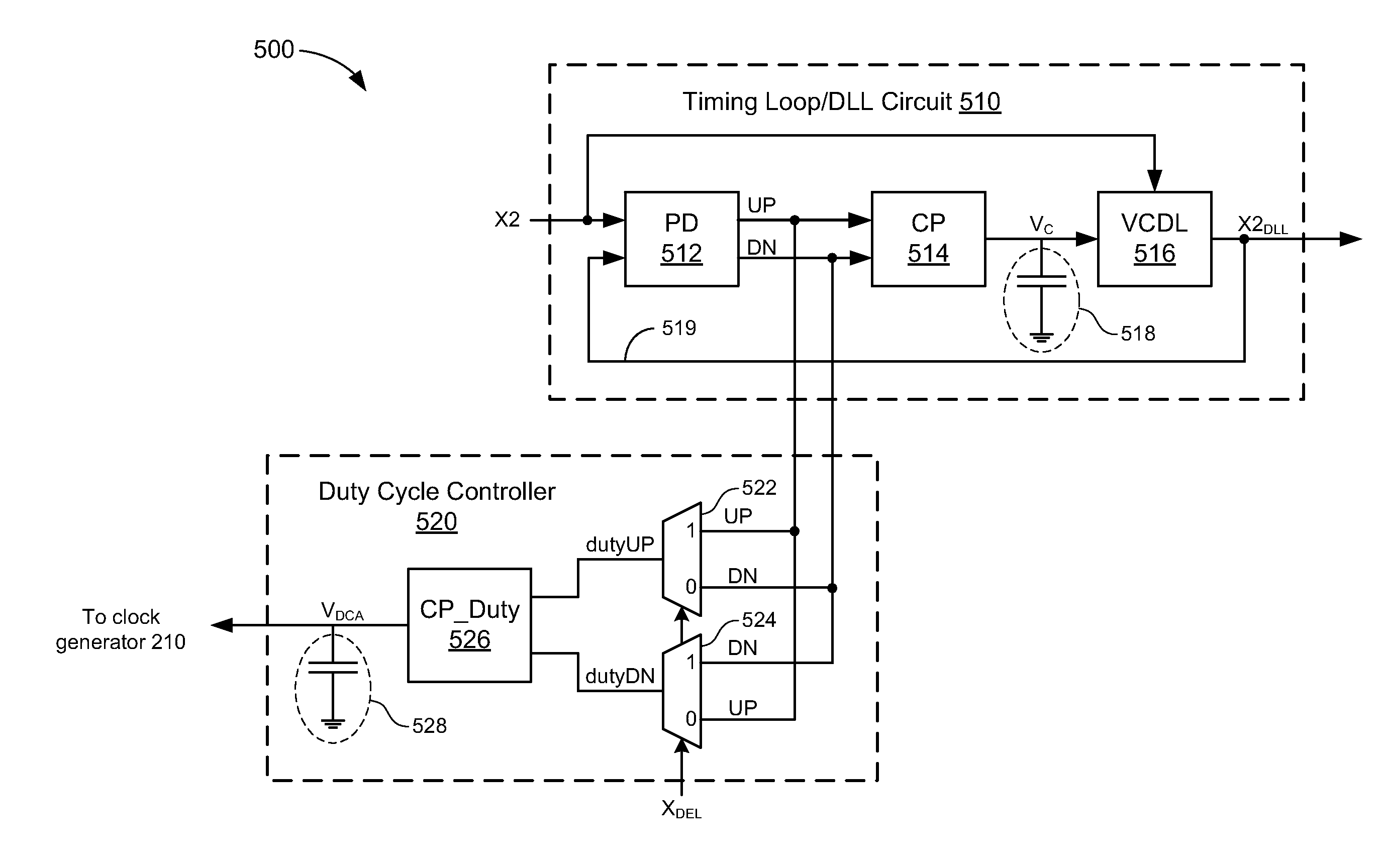
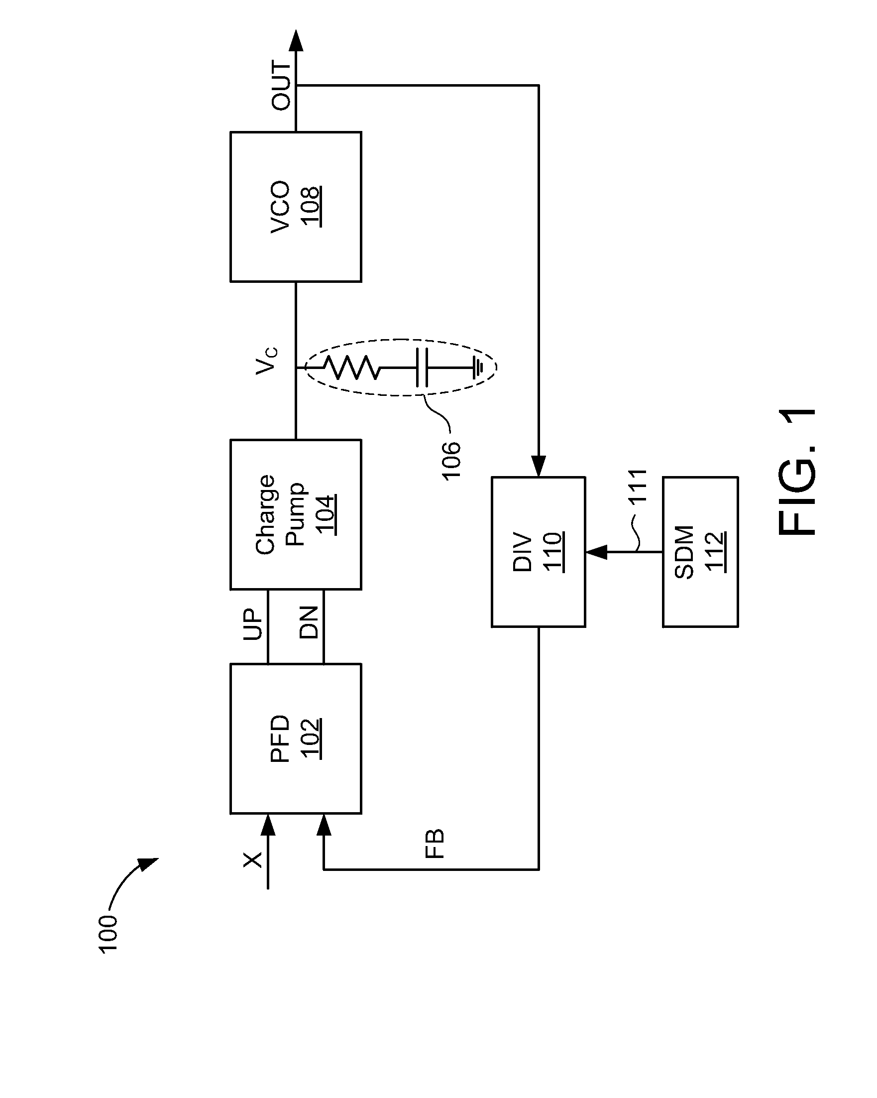
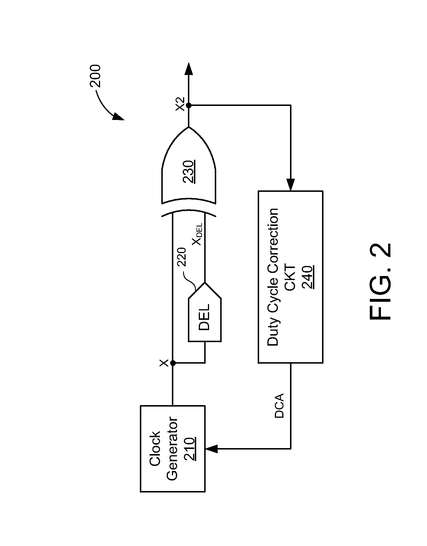
[0024]In the following description, numerous specific details are set forth such as examples of specific components, circuits, and processes to provide a thorough understanding of the present disclosure. The term “coupled” as used herein means connected directly to or connected through one or more intervening components or circuits. Also, in the following description and for purposes of explanation, specific nomenclature is set forth to provide a thorough understanding of the present embodiments. However, it will be apparent to one skilled in the art that these specific details may not be required to practice the present embodiments. In other instances, well-known circuits and devices are shown in block diagram form to avoid obscuring the present disclosure. Any of the signals provided over various buses described herein may be time-multiplexed with other signals and provided over one or more common buses. Additionally, the interconnection between circuit elements or software blocks ma


PUM


Abstract

A frequency synthesizing system includes a clock generator to generate a reference clock signal, a frequency doubler to generate a frequency-doubled clock signal in response to rising edges and falling edges of the reference clock signal, a frequency multiplier to generate a frequency-multiplied clock signal in response to either rising edges or falling edges of the frequency-doubled clock signal, and a fractional-N synthesizer coupled to the frequency multiplier to generate an output clock signal in response to the frequency-multiplied clock signal.

Description


Claims


Application Information

Patent Timeline
Owner QUALCOMM INC
Why Eureka
Try Eureka