Oscillation clock capable of automatically adjusting frequency and generated inside chip and designing method thereof

A technology of oscillating clocks and clocks, which is applied in the field of chip circuit design, can solve problems such as high error rate, loss of manufacturers and users, and rising costs, and achieve the effect of stable chip operation, compact structure, and reduced error rate

Inactive Publication Date: 2013-04-03
WUXI ADVANCE SUNRISE
View PDF6 Cites 0 Cited by
  • Summary
  • Abstract
  • Description
  • Claims
  • Application Information

AI Technical Summary

Problems solved by technology

Edge phenomena can easily lead to problems such as unstable chip operation and high error r

Method used


Image

  • Oscillation clock capable of automatically adjusting frequency and generated inside chip and designing method thereof
  • Oscillation clock capable of automatically adjusting frequency and generated inside chip and designing method thereof

Examples


Embodiment Construction

[0016] The present invention will be further described below in conjunction with specific drawings and embodiments.

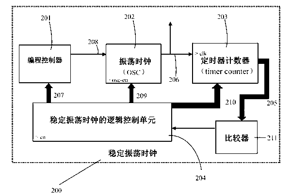
[0017] figure 1 As shown: the stable oscillating clock 200 generated inside the chip at least includes an oscillating clock generator (OSC generator) 202, a programming controller 201 for controlling clocks of different frequencies, a timing counter 203, a comparator 211 and a stable The logic control unit 204 of the oscillating clock. The programming control signal 208 is directly connected to the oscillation clock generator (OSC generator) 202 to control the frequency of the corresponding oscillation clock generator. The oscillating clock signal is generated by an oscillating clock generator. The oscillating clock signal is output to the outside for use by different parts of the chip. The oscillating clock signal 206 is connected to the clock input end of the timer counter 203 to adjust how many times the timer counter counts. The count 205 of the counter is


PUM


Abstract

The invention provides a stable oscillation clock generated inside a chip, at least comprising an oscillation clock generator (OSC generator), a programming controller for controlling clocks with different frequencies and a timing counter, wherein a control signal output by the programming controller for controlling the clocks with the different frequencies is directly connected to the oscillation clock generator (OSC generator); an oscillation clock signal is generated by the oscillation clock generator; the oscillation clock signal is output to outside to be used by different parts of the chip; the oscillation clock signal is connected to the clock input end of the timing counter to adjust the counted quantity of the timing counter; and the counted quantity of the timing counter is connected to a comparator to be compared with a standard performance to generate a feedback signal to a logic control unit of the stable oscillation clock, so as to automatically determine the frequency of the oscillation clock. A designing method of the stable oscillation clock generated inside the chip enables the work of the chip to be more stable and reduces the error rate and the like; and the stable oscillation clock is compact in structure and is safe and reliable.

Description


Claims


Application Information

Patent Timeline
Owner WUXI ADVANCE SUNRISE
Why Eureka
Try Eureka