MRAM sense amplifier for offsetting deviation

A technology of sense amplifiers and amplifiers, used in instruments, static memory, digital memory information, etc., can solve problems such as inconvenience and affect speed, and achieve the effect of easy product design and flexible configuration

Active Publication Date: 2019-12-10
SHANGHAI CIYU INFORMATION TECH
View PDF1 Cites 0 Cited by
  • Summary
  • Abstract
  • Description
  • Claims
  • Application Information

AI Technical Summary

Benefits of technology

This patented technology describes an improved method called this sensor used by magnetic storage devices (MRA). In its current form, it uses only one bit per memory cell instead of twice or four times compared to previous methods like error correction codes (ECCs), allowing for greater flexibility when configuring sensors while still maintaining their performance at high speeds.

Problems solved by technology

This patented describes how magnetoresistive random access memories (MSNAND) operate at different speeds depending upon their specific characteristics. However, they require accurate measurements during programming and erasing, leading to errors when measuring resistance values. To solve this problem, certain methods were developed including feedback loops and time division techniques. These solutions involve connecting both reference elements and recording signals onto separate areas within the memory element itself instead of directly accessing these components individually.

Method used


Image

  • MRAM sense amplifier for offsetting deviation
  • MRAM sense amplifier for offsetting deviation
  • MRAM sense amplifier for offsetting deviation

Examples


Embodiment Construction

[0038] The preferred embodiments of the present invention are described in detail below, so that the advantages and features of the present invention can be more easily understood by those skilled in the art, so as to define the protection scope of the present invention more clearly.

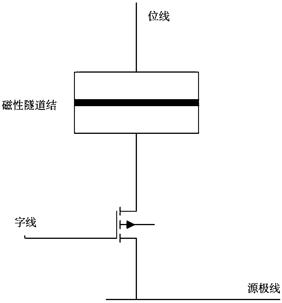
[0039] The MRAM readout circuit includes a front-stage circuit and a post-stage circuit that convert the difference between a memory cell and a reference resistance into a voltage signal. A typical pre-stage circuit such as Figure 6 Shown, including current mirror, reference cell group and control current limit cell. Figure 6 The output of the preceding stage circuit is shown as the input of the subsequent stage circuit.

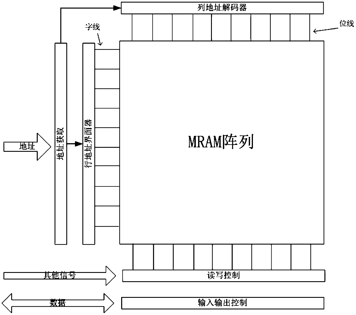
[0040] If a chip needs to read many cells at the same time, Figure 6The circuit can be extended in parallel, and one pair of reference units can be shared by all standby units. Future control statistics deviation can also increase reference units through parallel expansion.


PUM


Abstract

The invention discloses an MRAM (Magnetic Random Access Memory) sense amplifier capable of offsetting deviation. The MRAM read-out circuit is used as a post-amplifier of the MRAM read-out circuit, andcomprises NMOS tubes M0 and M1 with the same parameters, NMOS tubes M2 and M3 with the same parameters, PMOS tubes M4 and M5 with the same parameters, capacitors C0 and C1, and three same switches K1and K2; the drain electrode of the M2 is connected with the drain electrode of the M4, wherein the connection point is a point A; the grid of M2 is connected with the grid of M4, wherein the connection point is a point B; the drain of M3 is connected with the drain of M5, wherein the connection point is a point C; the grid of M3 is connected with the grid of M5, wherein the connection point is apoint D; the capacitor C0 is connected between the point B and the point C, and the capacitor C1 is connected between the point A and the point D. In the working stage, the capacitor C0 and the capacitor C1 counteract asymmetry of the read-out differential amplifier. A pair of capacitors is added on the basis of a common differential comparator, asymmetry of the differential amplifier can be counteracted, and meanwhile the area of the amplifier does not need to be large.

Description


Claims


Application Information

Patent Timeline
Owner SHANGHAI CIYU INFORMATION TECH
Why Eureka
Try Eureka