Shift control device for continuously variable transmission

a technology of control device and transmission, which is applied in the direction of gearing control, gearing element, belt/chain/gearing, etc., can solve the problem that the controller may create a hysteresis regarding the stepped operation amount, and achieve the effect of reducing the uncomfortable sensation of the driver

Active Publication Date: 2015-06-04
SUBARU CORP
View PDF9 Cites 5 Cited by
  • Summary
  • Abstract
  • Description
  • Claims
  • Application Information

AI Technical Summary

Benefits of technology

The technical effect of this patented technology is that it provides a way to make sure that the vehicle's transmission shifts between different gears without causing discomfort or even getting stuck at certain points during operation.

Problems solved by technology

The technical problem addressed in this patent text relates to improving the comfort experienced for drivers while controlling the gear ratio in vehicles equipped with continuous variators. Specifically, conventional methods like adjusting the gears manually through a lever mechanism require frequent repositioning of the accelerator pedals, leading to discomfort and increased fuel consumption. Additionally, existing methods often lead to incorrect gear selection due to insufficient gear reduction during upshifts, causing unnecessary acceleration.

Method used


Image

  • Shift control device for continuously variable transmission
  • Shift control device for continuously variable transmission
  • Shift control device for continuously variable transmission

Examples


Embodiment Construction

[0023]An implementation of the present invention will be described in detail with reference to the drawings. Components which are the same in multiple drawings are denoted with the same reference numerals, and redundant description thereof will be omitted.

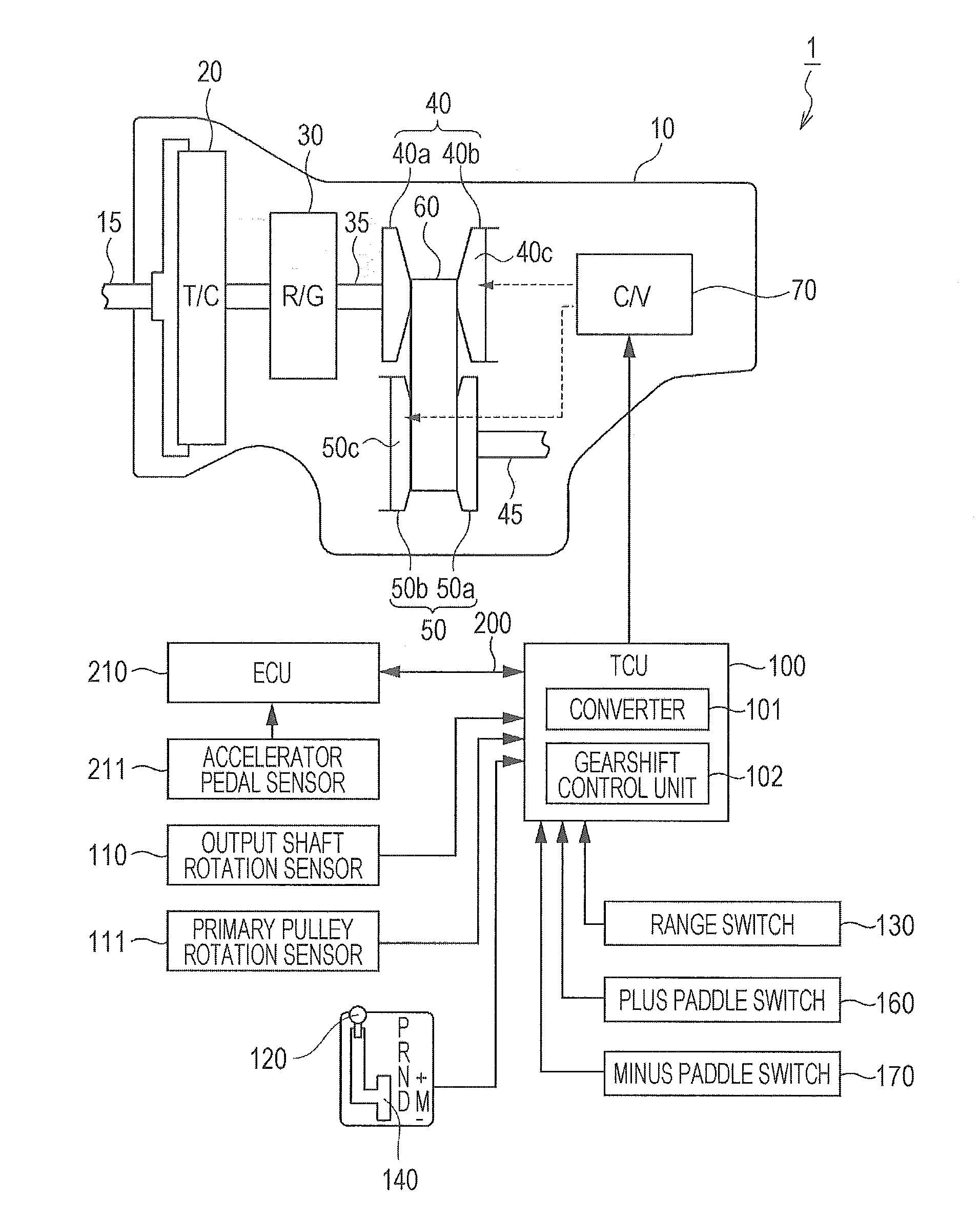
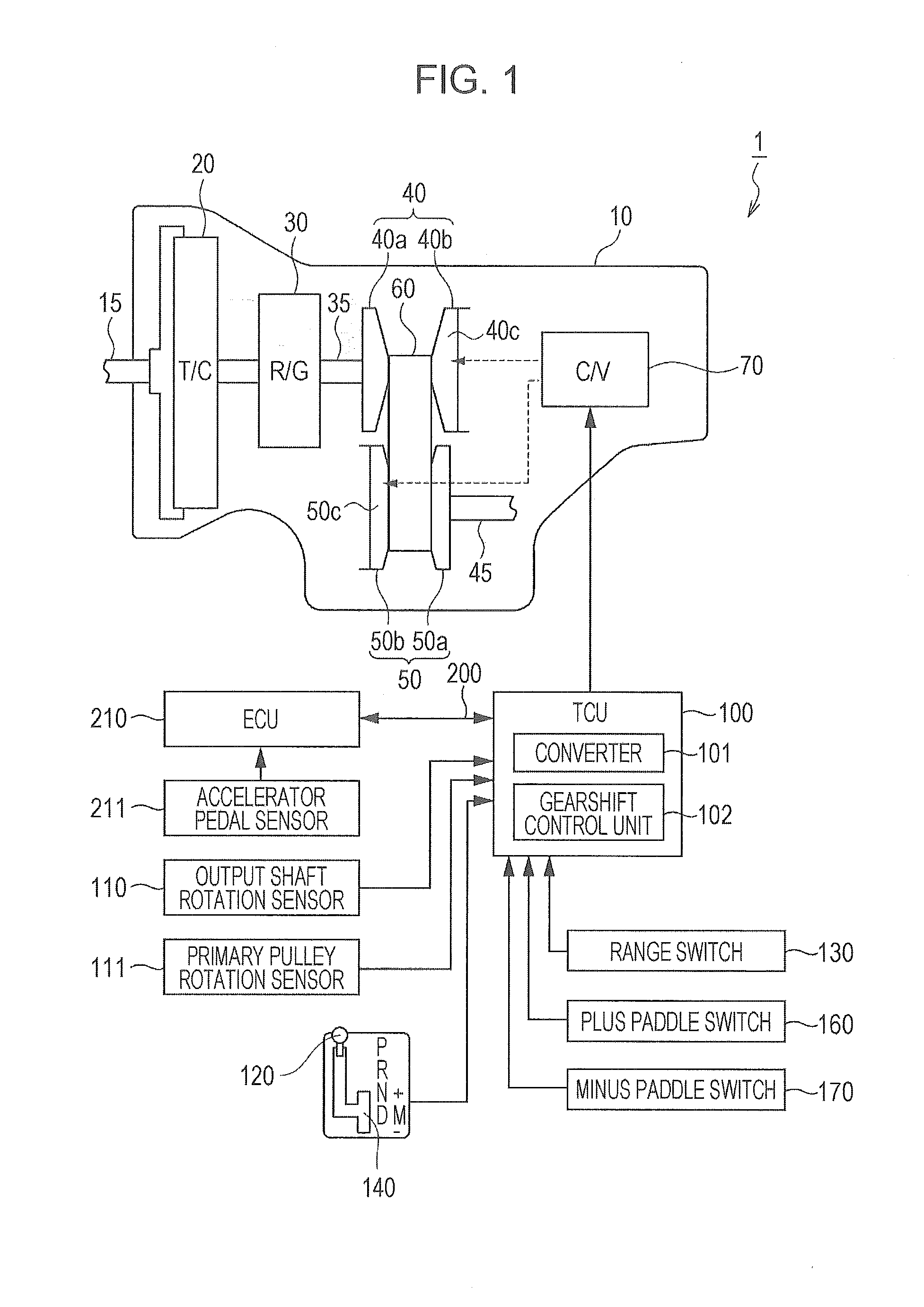
[0024]First, the configuration of a shift control device 1 of a continuously variable transmission according to the implementation will be described with reference to FIG. 1. FIG. 1 is a block diagram illustrating the configuration of the shift control device 1 for a continuously variable transmission according to the present invention, and a continuously variable transmission 10 to which the shift control device 1 has been applied.

[0025]The continuously variable transmission 10 is a continuously variable transmission which automatically and steplessly changes the gear ratio, in accordance with the running state of the vehicle. The continuously variable transmission 10 is connected to an output shaft 15 of an engine, so as to convert


PUM


Abstract

A transmission control device includes a converter that converts continuous accelerator positions detected by an accelerator pedal sensor into a stepped step position, and a controller that controls the gear ratio of a continuously variable transmission based on the converted step position. The converter creates a hysteresis regarding the converted step position, when the accelerator depression amount increases, and when the accelerator depression amount decreases. In the case where the step position reaches a predetermined position or greater, the controller executes kick-down control where the gear ratio is controlled to a low side.

Description


Claims


Application Information

Patent Timeline
Owner SUBARU CORP
Why Eureka
Try Eureka