Dual clutch gearbox with countershaft design

Active Publication Date: 2015-10-15
ZF FRIEDRICHSHAFEN AG
View PDF5 Cites 17 Cited by
  • Summary
  • Abstract
  • Description
  • Claims
  • Application Information

AI Technical Summary

Benefits of technology

[0017]In a further embodiment of the invention, the bridging gearwheel plane for the group transmission can be arranged before the group transmission in the force flow direction during traction operation, so that the sixth loose gear wheel is arranged on the drive output shaft of the main transmission, it can be detachably connected by means of the tenth interlocking shifting element to the carrier and hence to the drive output of the planetary transmission, and it meshes with the eighth fixed gear wheel arranged on the second countershaft. This design has the advantage that the second countershaft is made shorter so that the diameter of the ring gear of the planetary transmission does not determine the axial distance.
[0018]In this case the ring gear of the planetary transmission can be detachably connected by means of an eleventh interlocking shifting element to the carrier of the planetary transmission, so that when the eleventh shifting e

Problems solved by technology

Disadvantageously, a non-powershifted group change takes a long time since a switchover in the group transmission

Method used


Image

  • Dual clutch gearbox with countershaft design
  • Dual clutch gearbox with countershaft design
  • Dual clutch gearbox with countershaft design

Examples


Embodiment Construction

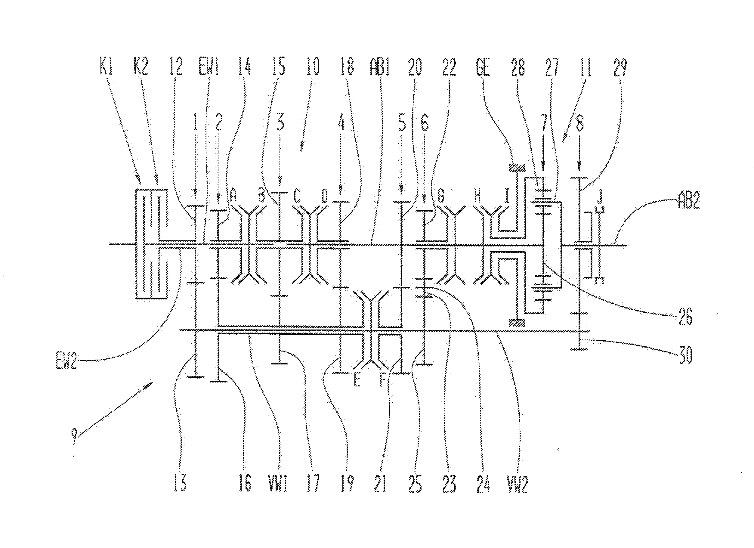
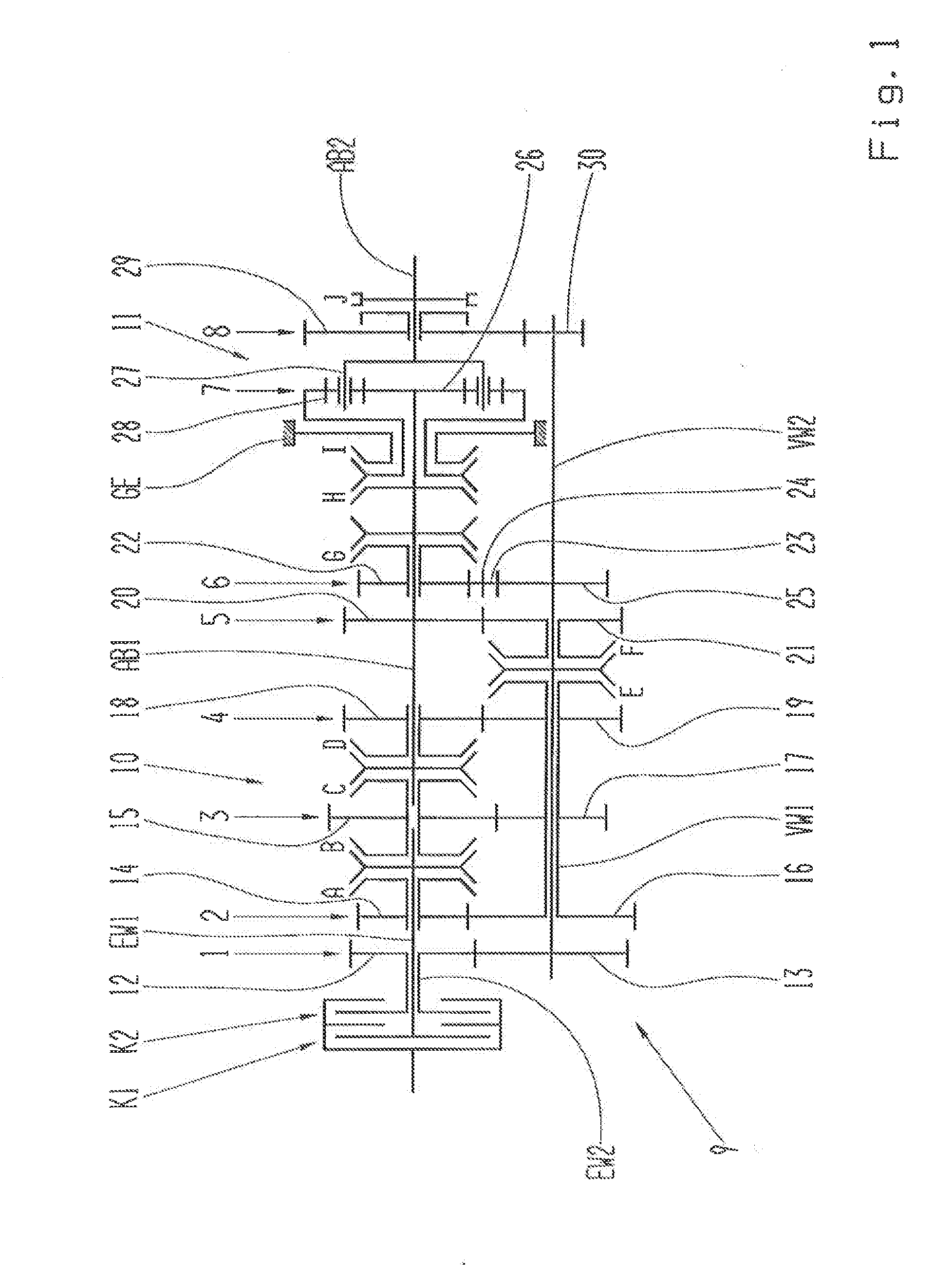
[0031]The structure of dual-clutch transmissions of countershaft design is already well known to those with knowledge of the subject, so that in the figure descriptions only the components relevant to the invention will be described and explained in detail. The same indexes are used for the same components.

[0032]FIG. 1 shows a dual-clutch transmission 9 of countershaft design, comprising a main transmission 10 and a group transmission 11 connected downstream from the main transmission 10, wherein the main transmission 10 comprises a first transmission input shaft EW1 in the form of a solid shaft connected to the drive output side of a first powershiftable clutch K1 which is associated with a first partial transmission, and a second transmission input shaft EW2 in the form of a hollow shaft connected to the drive output side of a second powershiftable clutch K2, through which shaft the first transmission input shaft EW1 passes, and which is associated with a second partial transmission,


PUM


Abstract

A dual-clutch transmission of a countershaft design includes a main transmission and a downstream group transmission. The main transmission has a solid first transmission input shaft connected to the output of a first powershiftable clutch, a hollow second transmission input shaft connected to the output of a second powershiftable clutch/electric machine, through which the first transmission input shaft extends, and two countershafts arranged coaxially with one another. The first countershaft is a hollow shaft and the second countershaft passes through the first countershaft. A drive output shaft of the main transmission is arranged coaxially with the two transmission input shafts and is the drive input shaft of the group transmission. The drive input sides of the powershiftable clutches/machines are connected to a drive aggregate, and to bridge across the group transmission, the second countershaft can be connected via a shifting element to the group transmission drive output.

Description


Claims


Application Information

Patent Timeline
Owner ZF FRIEDRICHSHAFEN AG
Why Eureka
Try Eureka