Combination Including a Ratchet Wrench and a Driving Member

Active Publication Date: 2016-03-03
HU BOBBY
View PDF7 Cites 8 Cited by
  • Summary
  • Abstract
  • Description
  • Claims
  • Application Information

AI Technical Summary

Benefits of technology

[0006]This need and other problems in the field of reliable ratchet wrenches

Problems solved by technology

When the ratchet wrench is directly coupled with a nut, the nut is apt to pass from an end of the ratchet wheel through the other end of the ratchet wheel, leading to inconvenience to a user, because the user has to keep the nut in the ratchet wheel while rotating the body.
However, the coupling force between the C-shaped retainer ring and the notches of the extension rod is insufficient such that the ratchet wheel is apt to slide relative to the extension rod.
As a result, the end of the extension rod is apt to extend from

Method used


Image

  • Combination Including a Ratchet Wrench and a Driving Member
  • Combination Including a Ratchet Wrench and a Driving Member
  • Combination Including a Ratchet Wrench and a Driving Member

Examples


Embodiment Construction

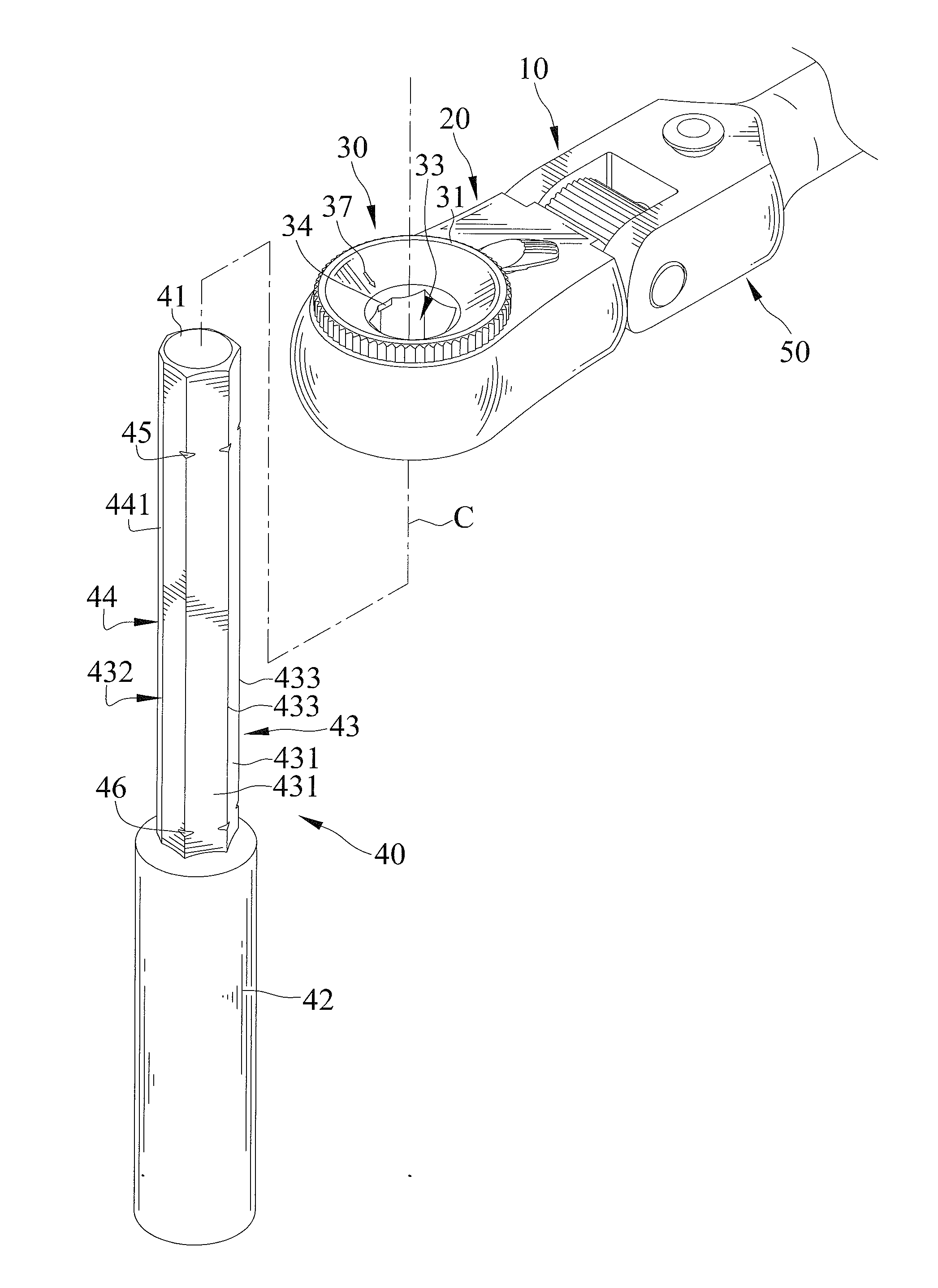
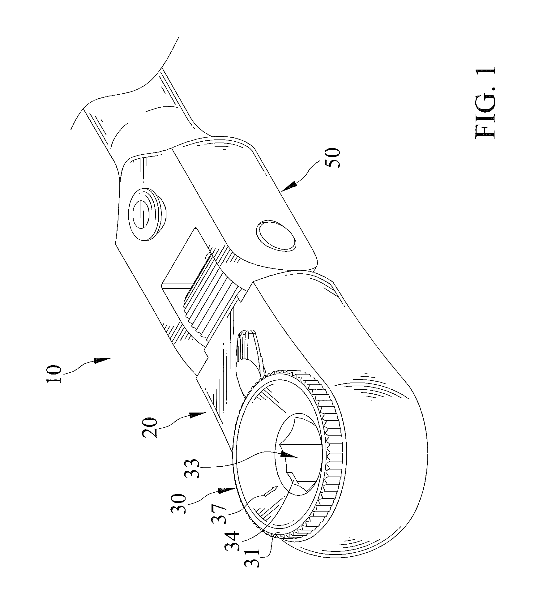
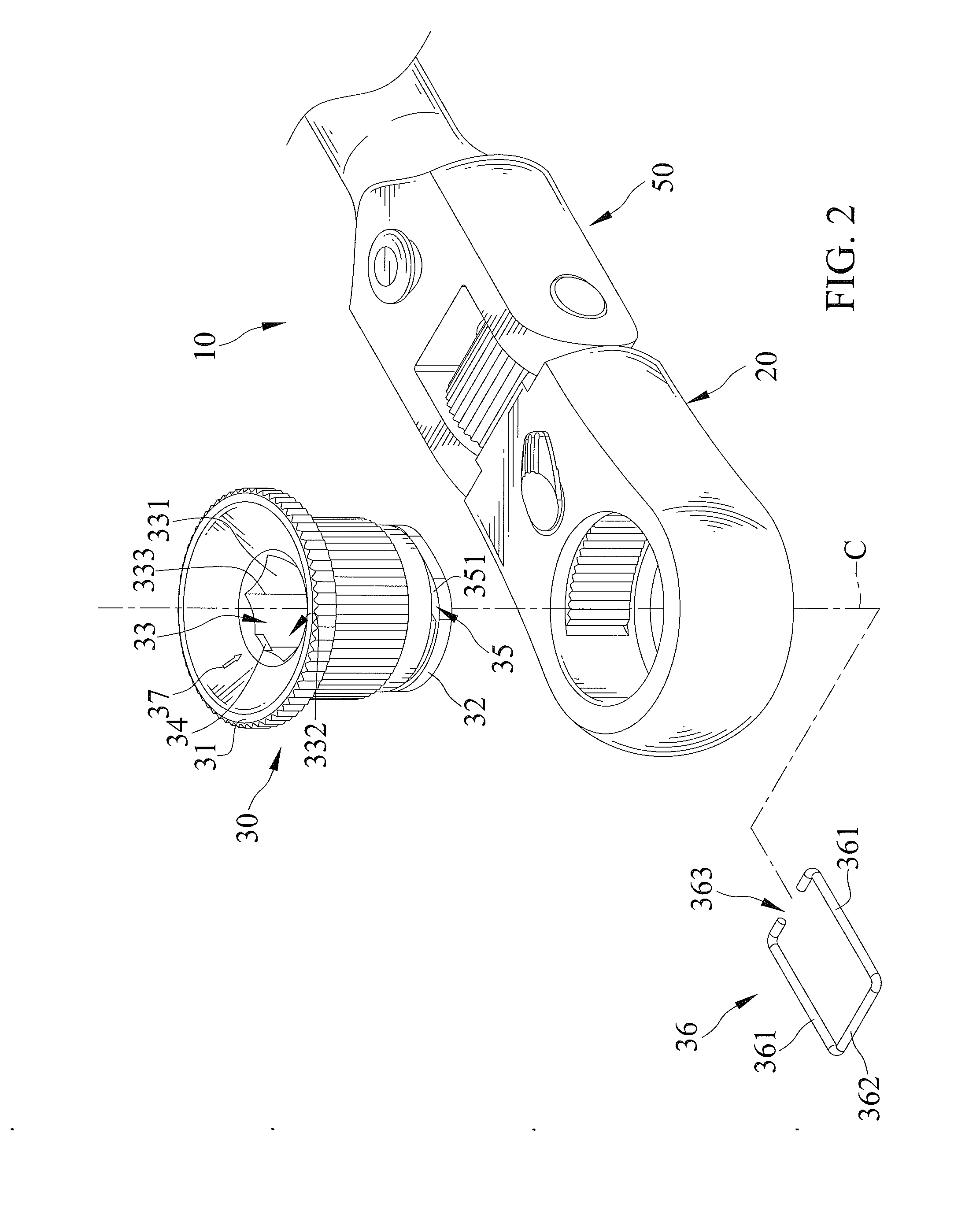
[0047]FIGS. 1-11 show a combination including a ratchet wrench 10 and a driving member 40 of a first embodiment according to the present invention. Ratchet wrench 10 includes a body 20, a ratchet wheel 30, and an operative portion 50.

[0048]Body 20 is pivotably connected to operative portion 50 and can be retained in a selected angular position relative to operative portion 50. Operative portion 50 is adapted to be gripped by a user.

[0049]Ratchet wheel 30 is mounted in body 20 and is rotatable about a rotational axis C relative to body 20. Ratchet wheel 30 includes a first side 31 and a second side 32 spaced from first side 31 along rotational axis C. Ratchet wheel 30 further includes a driving hole 33 extending from first side 31 through second side 32. Driving hole 33 is polygonal. In this embodiment, driving hole 33 includes an inner periphery 332 having a plurality of abutment surfaces 331 contiguous to each other and arranged along a circumferential direction about rotational axis


PUM


Abstract

A combination includes a ratchet wrench and a driving member. The ratchet wrench includes a body and a ratchet wheel mounted in the body and rotatable relative to the body about a rotational axis. A driving hole extends through from a side through the other side of the body along the rotational axis and includes an inner periphery having a plurality of abutment surfaces. A corner is formed between each two adjacent abutment surfaces. At least one limiting portion protrudes from the inner periphery of the driving hole in a radial direction perpendicular to the rotational axis. The driving member includes at least one evasive portion and is coupled to the driving hole. The driving member is movable between a first coupling position and a second coupling position along the rotational axis when the at least one evasive portion is aligned with the at least one limiting portion.

Description


Claims


Application Information

Patent Timeline
Owner HU BOBBY
Why Eureka
Try Eureka