Image processing apparatus that corrects contour, control method therefor, storage medium storing control program therefor, and image pickup apparatus
- Summary
- Abstract
- Description
- Claims
- Application Information
AI Technical Summary
Benefits of technology
Problems solved by technology
Method used
Image

Examples
first embodiment
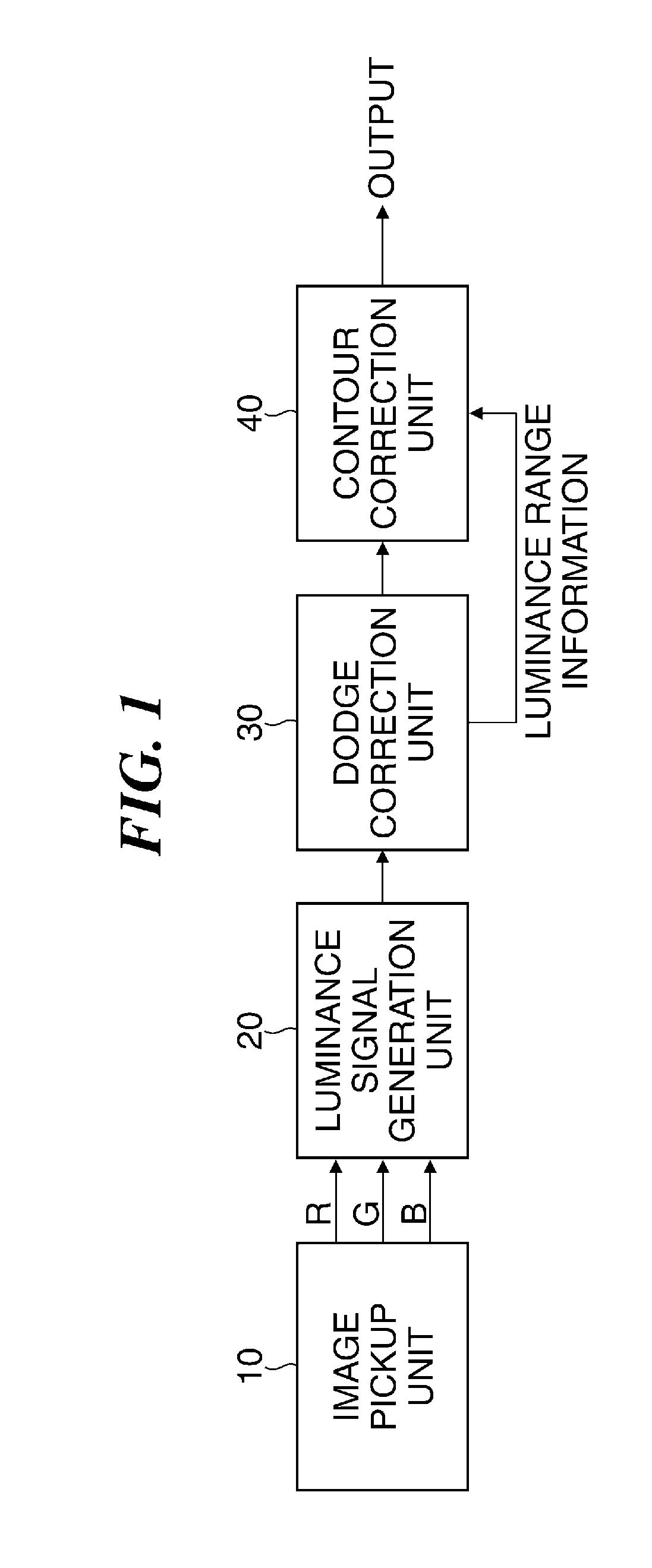
[0032]FIG. 1 is a block diagram schematically showing a configuration of an example of an image pickup apparatus equipped with an image processing apparatus according to the present invention.
[0033]The illustrated image pickup apparatus is a digital camera (hereinafter referred to as a camera, simply) that has an image pickup unit 10. The image pickup unit 10 has a photographing lens unit (hereinafter referred to as a photographing lens), an image pickup device, such as a CCD or a CMOS sensor, and a control unit, which are not shown. An optical image (object image) is formed on the image pickup device through the photographing lens. Then, the image pickup device outputs an analog signal corresponding to the optical image.
[0034]The control unit controls exposure, shutter speed, etc., A / D-converts the analog signal output from the image pickup device, and outputs RGB signals that represent image data. A luminance signal generation unit 20 receives the RGB signals, and generates a lumin
second embodiment
[0054]Next, one example of a camera according to the present invention will be described.
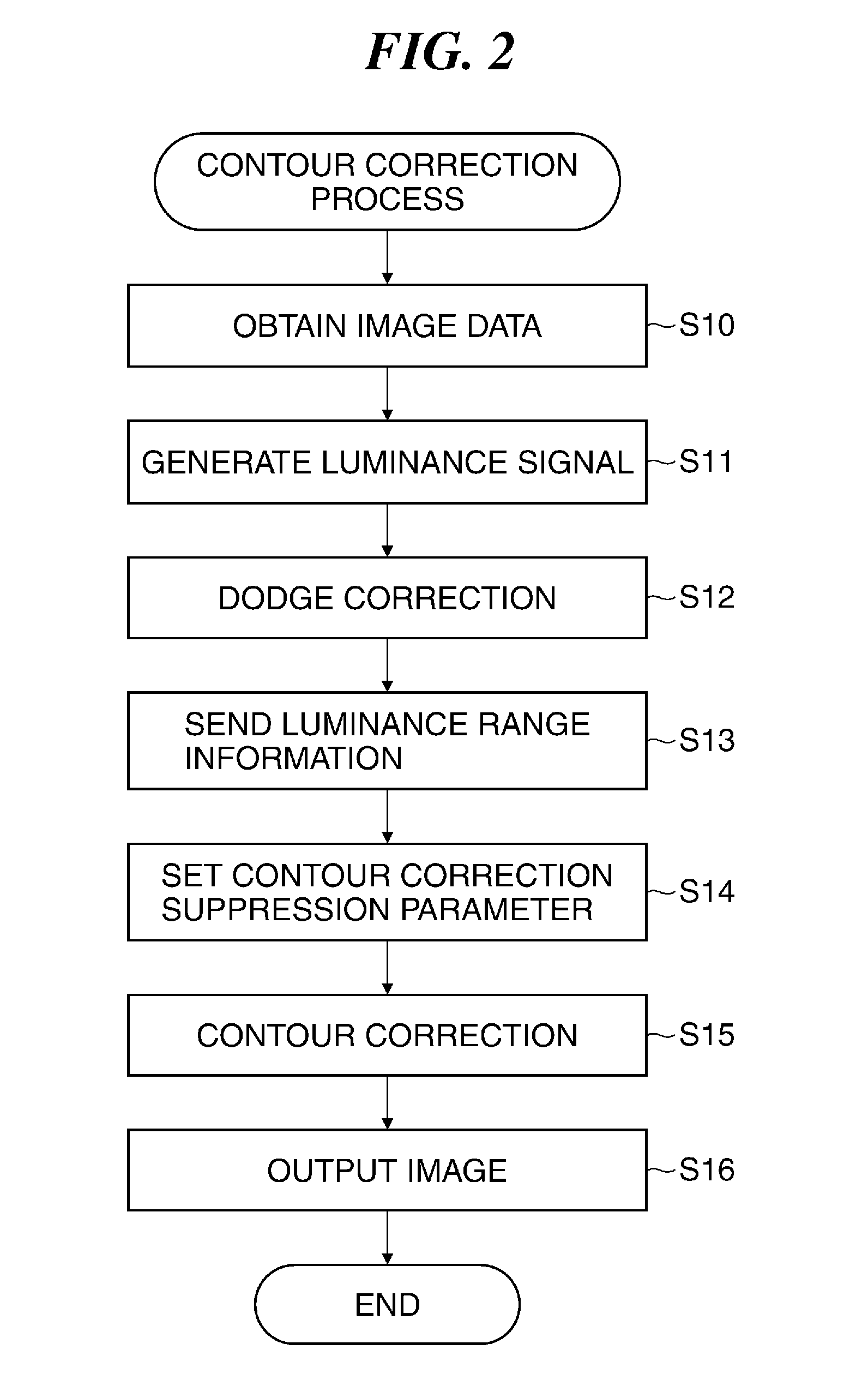
[0055]The configuration of the camera of the second embodiment is the same as the camera shown in FIG. 1. Moreover, the camera according to the second embodiment performs the contour correction process according to the flowchart shown in FIG. 2. It should be noted that the camera according to the second embodiment may arrange the contour correction unit 40 at the preceding stage of the dodge correction unit 30 as shown in FIG. 4.
[0056]FIG. 5A and FIG. 5B are graphs for describing a relationship between the dodge correction process and the contour correction process that are performed by the camera equipped with an image processing apparatus according to the second embodiment of the present invention.
[0057]The camera according to the second embodiment sets up first, second, third, and fourth parameters as the contour correction suppression parameters set up in the process in the step S14 shown in FI
third embodiment
[0069]Next, one example of a camera according to the present invention will be described.
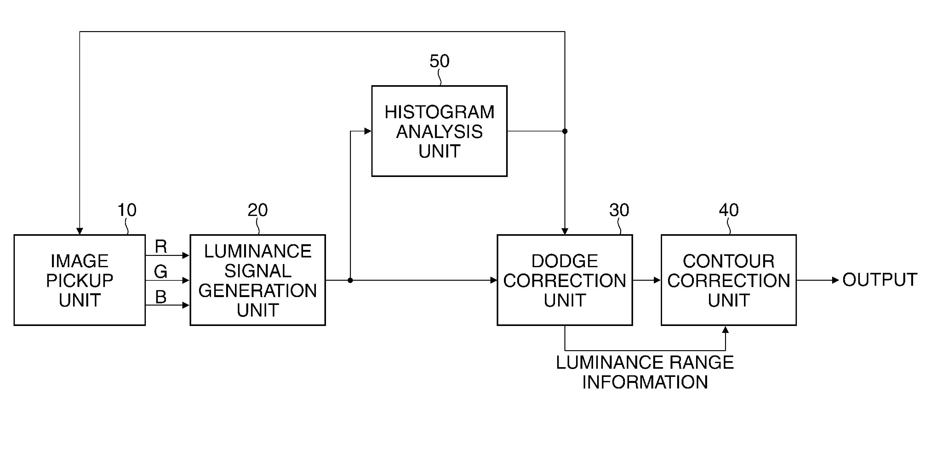
[0070]FIG. 6 is a block diagram schematically showing a configuration of the example of the camera according to the third embodiment of the present invention. It should be noted that components of the camera in FIG. 6 that are the same as the components of the camera in FIG. 1 are indicated by the same reference numbers and the descriptions thereof are omitted.
[0071]The camera in FIG. 6 is provided with a histogram analysis unit 50. The luminance signal output from the luminance signal generation unit 20 is given to the histogram analysis unit 50. The histogram analysis unit 50 obtains a histogram on the basis of the luminance values of the luminance signals in the luminance ranges. A horizontal axis and a vertical axis of the histogram respectively indicate a luminance value and a frequency. Then, the histogram analysis unit 50 analyzes the luminance signal (i.e., image data) on the basis of the h
PUM
 Abstract
Description
Claims
Application Information
 - R&D Engineer
- R&D Manager
- IP Professional
- Industry Leading Data Capabilities
- Powerful AI technology
- Patent DNA Extraction
Browse by: Latest US Patents, China's latest patents, Technical Efficacy Thesaurus, Application Domain, Technology Topic.
© 2024 PatSnap. All rights reserved.Legal|Privacy policy|Modern Slavery Act Transparency Statement|Sitemap