Exhaust gas purifying device for internal combustion engine
- Summary
- Abstract
- Description
- Claims
- Application Information
AI Technical Summary
Benefits of technology
Problems solved by technology
Method used
Image

Examples
first embodiment
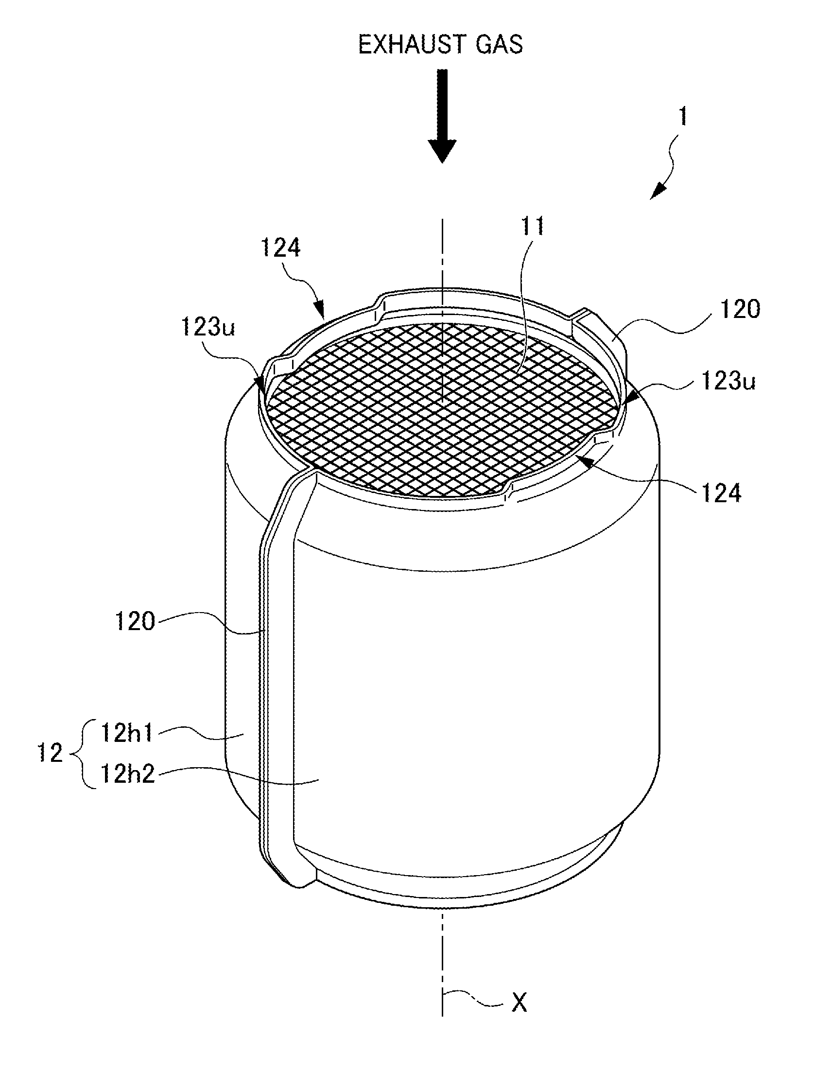
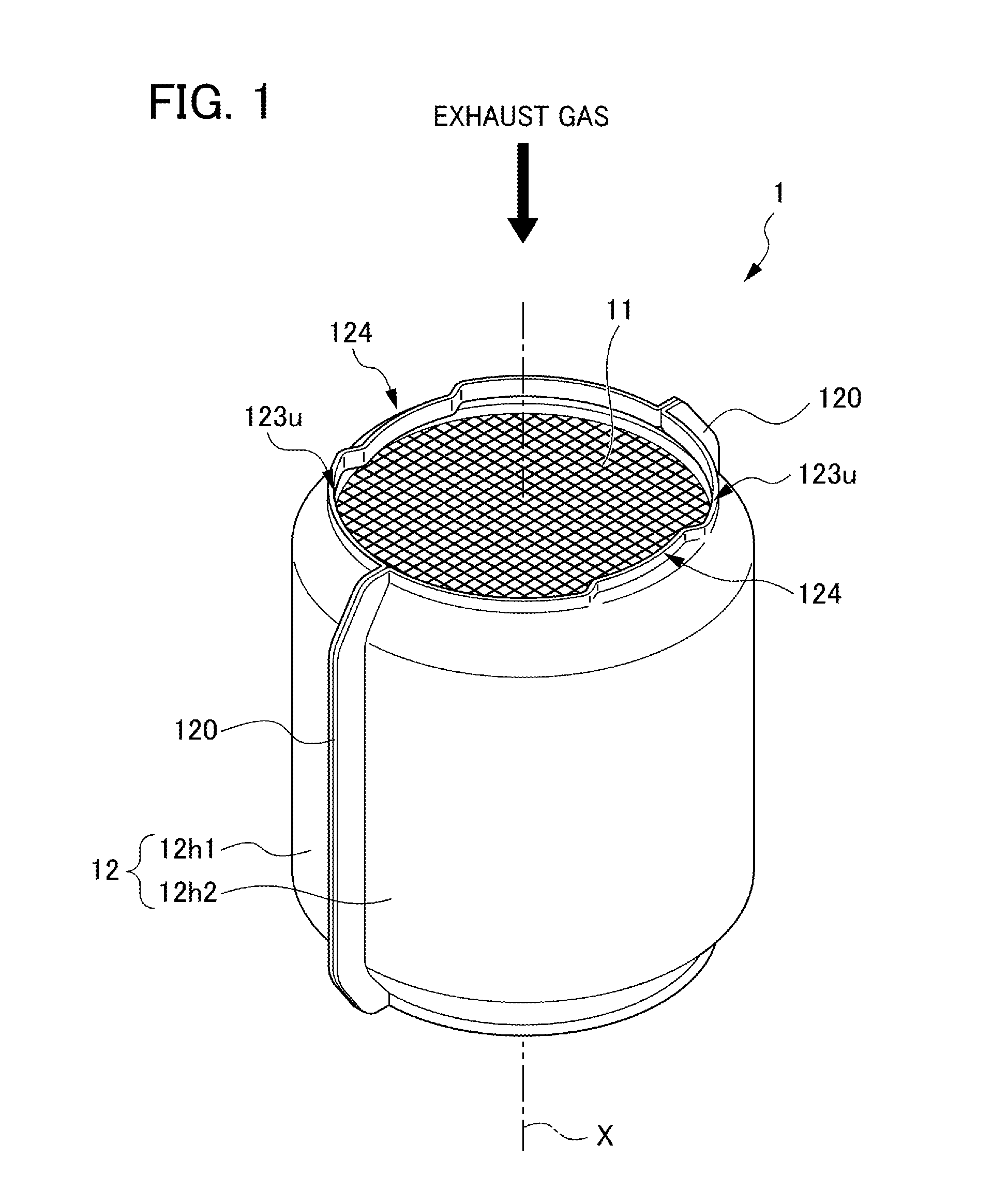
[0044]FIG. 1 is a perspective view of an exhaust gas purifying device for an internal combustion engine according to the first embodiment of the present invention. An exhaust gas purifying device 1 for an internal combustion engine according to the present embodiment is a gasoline particulate filter (hereinafter referred to as “GPF”) that is provided in the exhaust pipe of an internal combustion engine that is not illustrated (hereinafter referred to as “engine”), and collects particulate matter (hereinafter referred to as “PM”) in the exhaust gas flowing through the exhaust pipe.
[0045]The exhaust gas purifying device 1, in one embodiment thereof, is provided immediately under a gasoline engine that is not illustrated, in the exhaust pipe extending downwards along the lateral side on the vehicle forward side of the gasoline engine. In other words, the exhaust gas purifying device 1 is provided in the exhaust pipe in a state with the flow direction of exhaust gas pointing downwards.
[004
second embodiment
[0088]FIG. 5 is an axial-direction partial cross-sectional view of an exhaust gas purifying device according to a second embodiment of the present invention.
[0089]In FIG. 5, the same reference symbols are assigned to corresponding parts in the respective drawings of FIGS. 1 to 4 described earlier.
[0090]In the second embodiment of FIG. 5, the sloped part 121a of the case member 12 is configured as follows.
[0091]In other words, the sloped part 121a of the case member 12 made to include the sloped circumferential face part 125c and a tubular part 126c connected with this is formed over the entire circumference of the inlet-side terminal part 123u.
[0092]In more detail, the sloped part 121a of the case member 12 is configured to include the sloped circumferential face part 125c that is the circumferential face of cone shape formed to slope in the central axis X direction towards the leading end so as to follow the outer circumferential face of the sloped part 112a of the honeycomb carrier
third embodiment
[0096]FIG. 6 is an axial-direction partial cross-sectional view of an exhaust gas purifying device according to a third embodiment of the present invention.
[0097]In FIG. 6, the same reference symbols are assigned to corresponding parts in the respective drawings of FIGS. 1 to 4 described earlier.
[0098]In the third embodiment of FIG. 6, the case member 12 thereof is configured as follows. In other words, a sloped part 121a of the case member 12 made to include a sloped circumferential face part 125d of the case member 12, a flat part 127d connecting with this sloped circumferential face part 125d, and a tubular part 126a connecting with this flat part 127d is formed over the entire circumference of the inlet-side terminal part 123u.
[0099]In more detail, the sloped part 121a of the case member 12 is formed to include the sloped circumferential face part 125d formed to sloped in the central axis X direction towards the leading end so as to follow the outer circumferential face of the slo
PUM
| Property | Measurement | Unit |
|---|---|---|
| Diameter | aaaaa | aaaaa |
| Length | aaaaa | aaaaa |
| Size | aaaaa | aaaaa |
Abstract
Description
Claims
Application Information
 - R&D Engineer
- R&D Manager
- IP Professional
- Industry Leading Data Capabilities
- Powerful AI technology
- Patent DNA Extraction
Browse by: Latest US Patents, China's latest patents, Technical Efficacy Thesaurus, Application Domain, Technology Topic.
© 2024 PatSnap. All rights reserved.Legal|Privacy policy|Modern Slavery Act Transparency Statement|Sitemap