Redox flow battery system and method for operating redox flow battery

a redox flow battery and flow system technology, applied in the direction of electrolyte stream management, indirect fuel cells, electrochemical generators, etc., can solve the problems of battery efficiency decline and pump loss, and achieve the effect of suppressing overcharge and overdischarge of electrolytes

Inactive Publication Date: 2017-01-12
SUMITOMO ELECTRIC IND LTD
View PDF9 Cites 8 Cited by
  • Summary
  • Abstract
  • Description
  • Claims
  • Application Information

AI Technical Summary

Benefits of technology

The inventors have developed an improved way to prevent excessive charging or discharges from happening during operation of batteries used with this new type of energy storage device (RFB). This results in better performance and longer lifespans on these devices compared to older designs that had no technical effect.

Problems solved by technology

This patented technical problem addressed in this patents relates to reducing pump loss during operation of redoxic flow batterles due to variations between different chargings levels or even when changing from one type of charged mode to another.

Method used


Image

  • Redox flow battery system and method for operating redox flow battery
  • Redox flow battery system and method for operating redox flow battery
  • Redox flow battery system and method for operating redox flow battery

Examples


first embodiment

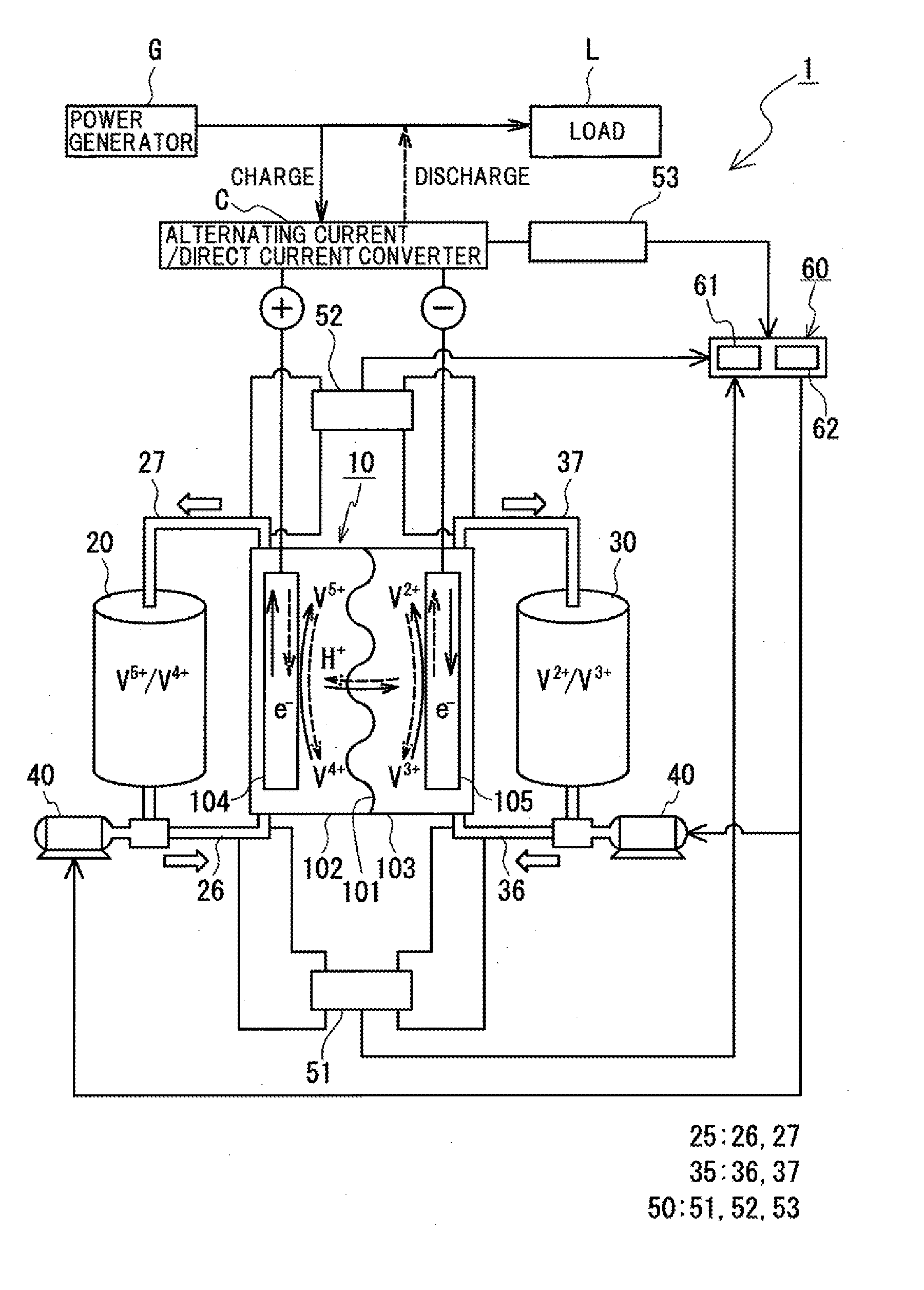
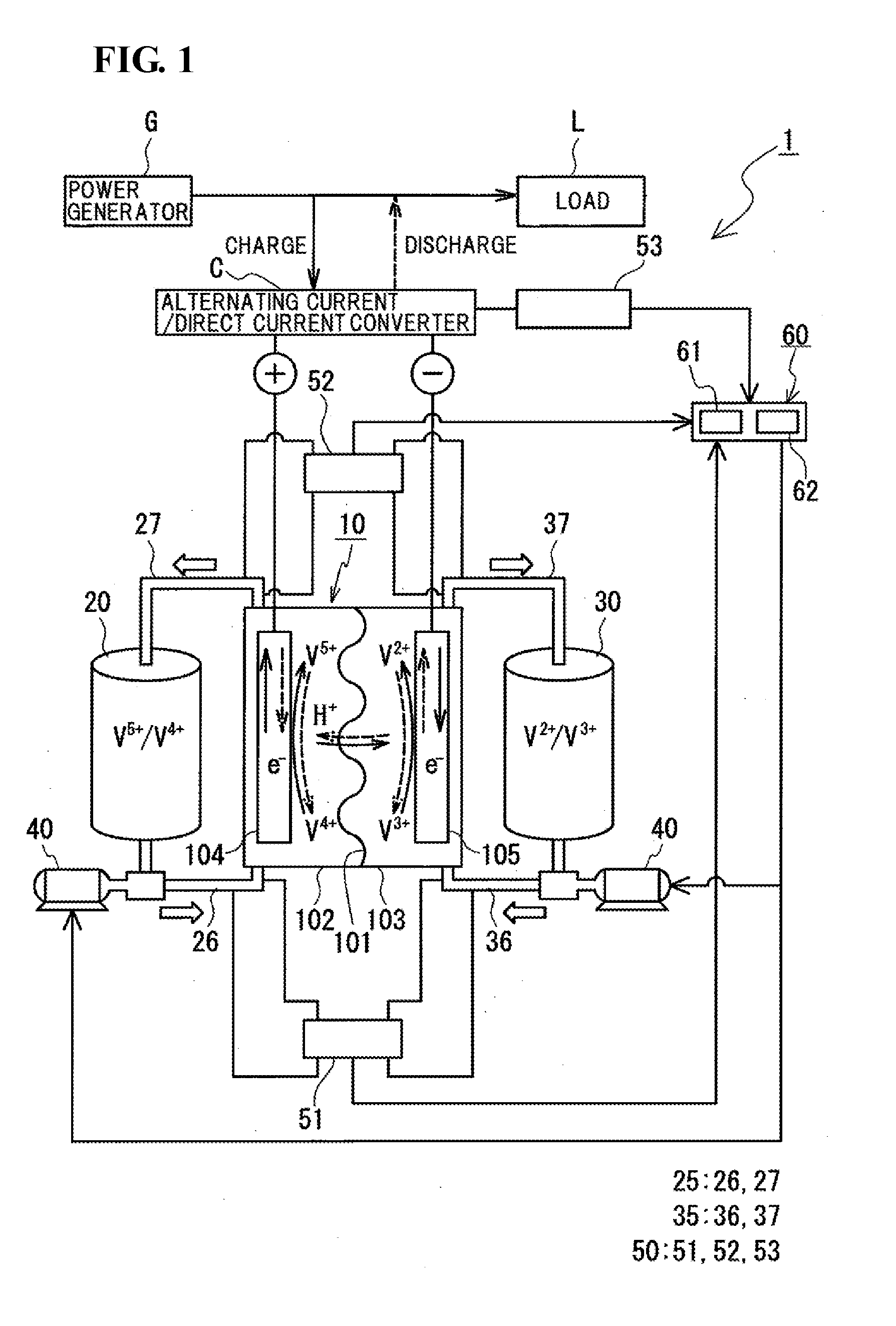
[0044]An RF battery system 1 according to a first embodiment is described with reference to FIGS. 1 and 2. The RF battery system 1 of FIG. 1 is, as is the case with the related art, connected between a power generator G (such as, for example, a photovoltaic power generator, a wind power generator, or another general power plant) and a load L (power system or customer) through an alternating current / direct current converter C so as to charge the power supplied from the power generator G and discharge the accumulated power to supply the power to the load L. Furthermore, the RF battery system 1 includes a battery cell 10 and a circulation mechanism (tanks, pipes, and pumps) that supplies electrolytes to the battery cell 10.

(The Battery Cell and the Circulation Mechanism)

[0045]The RF battery system 1 includes the battery cell 10. The battery cell 10 is partitioned into a positive-electrode cell 102 and a negative-electrode cell 103 by a membrane 101 formed of an ion-permeable membrane. A

second embodiment

[0070]An RF battery system according to a second embodiment is described with reference to FIGS. 3 and 4. Compared to the RF battery system 1 of FIG. 1 according to the first embodiment, an RF battery system 1A of FIG. 3 according to the second embodiment further includes a terminal voltage measurement unit 54, and the pump controller 60 further includes a terminal voltage determination unit 64. Hereafter, the RF battery system 1A according to the second embodiment is described by mainly describing the difference between the first embodiment and the RF battery system 1A according to the second embodiment while description of similar structures is omitted.

(The Terminal Voltage Measurement Unit)

[0071]The terminal voltage measurement unit 54 measures a terminal voltage (Vt) of the battery cell 10. According to the present example, the terminal voltage measurement unit 54 utilizes a voltmeter and is provided in the alternating current / direct current converter C (power converter). The mea


PUM


Abstract

Provided are a redox flow battery system and a method for operating a redox flow battery that suppress overcharge and overdischarge of an electrolyte.
A redox flow battery system includes a pump that supplies an electrolyte to a battery cell by circulation, a pump controller that controls a flow rate of the pump, and a measurement unit that measures at least two parameters selected from among an inlet-side state of charge of the electrolyte supplied to the battery cell, an outlet-side state of charge of the electrolyte drained from the battery cell, and a charge/discharge current input to/output from the battery cell. The pump controller includes a pump flow-rate computation unit that calculates a charge/discharge efficiency of the battery cell from the parameters measured by the measurement unit and, based on the charge/discharge efficiency, determines the flow rate of the pump so that the electrolyte drained from the battery cell is neither overcharged nor overdischarged. The pump controller also includes a pump flow-rate instruction unit that sets in the pump the flow rate determined by the pump flow-rate computation unit.

Description


Claims


Application Information

Patent Timeline
Owner SUMITOMO ELECTRIC IND LTD
Why Eureka
Try Eureka