Foreign material removal device

Active Publication Date: 2017-02-02
KOITO MFG CO LTD
View PDF1 Cites 15 Cited by
  • Summary
  • Abstract
  • Description
  • Claims
  • Application Information

AI Technical Summary

Benefits of technology

[0038]According to the present invention, as the piston is moved relative to the cylinder, high-pressure air is fed from the cylinder and is injected from the nozzle. Therefore, it is possible to ensure the structural simplification or the efficient injection state of high-pressure air from the nozzle.

Problems solved by technology

An imaging unit of the in-vehicle camera is often contaminated by mud scattered by the driving of the vehicle or water droplets attached during rainy weather driving or the like.
Thus, the video displayed on the display is blurred, which may cause a problem of interfering the checking.
Depending on the structure of the mechanism, the structure becomes complicated, and thus, manufacturing cost is increased.
Therefore, structural simplification or an efficient injection state of high-pressure air from the nozzle may not be ensured in Patent Document 1.

Method used


Image

  • Foreign material removal device
  • Foreign material removal device
  • Foreign material removal device

Examples


Example

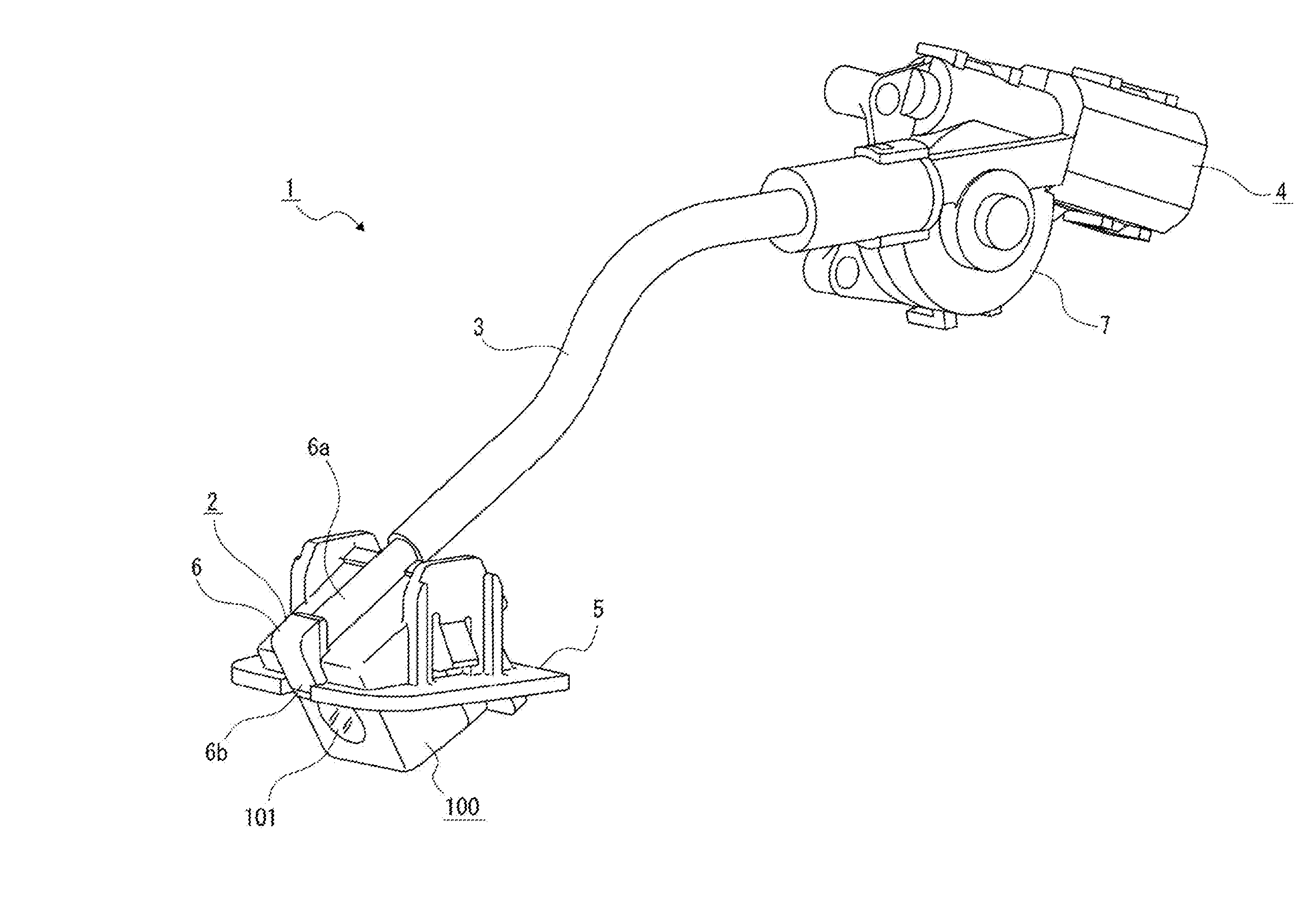
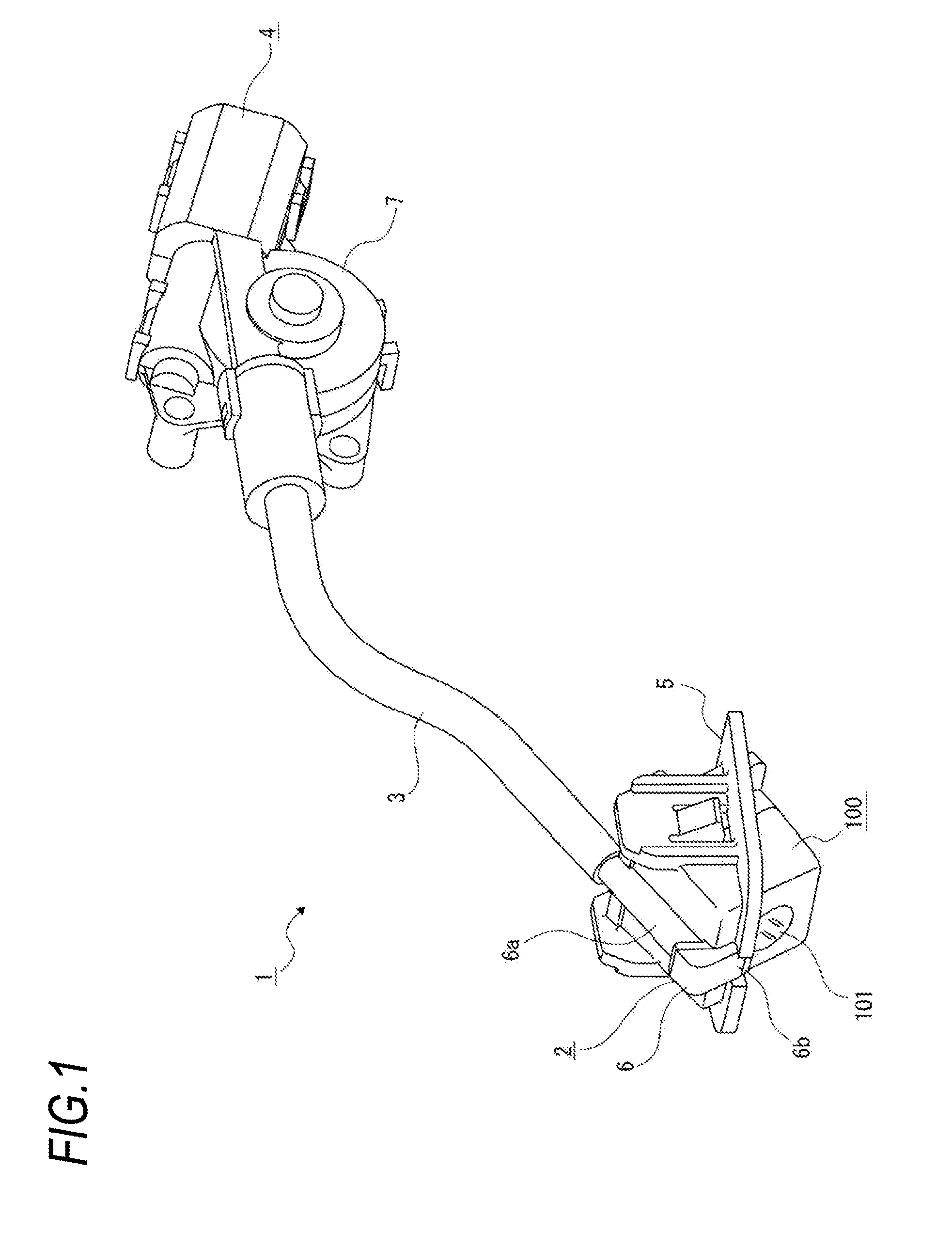
[0057]Hereinafter, an embodiment of a foreign material removal device of the present invention will be described with reference to the accompanying drawings.

[0058]Further, in the following, an example where the foreign material removal device of the present invention is applied to a device for removing foreign material attached to an in-vehicle camera has been described. However, the foreign material removal device of the present invention is not limited to be applied to the device for removing foreign material attached to the in-vehicle camera. The foreign material removal device of the present invention is widely applicable as a device for removing foreign material attached to various structures, in particular, as a foreign material removal device for removing foreign material attached to a structure provided in a vehicle, such as a vehicle lamp, a window, a mirror and a collision prevention sensor.

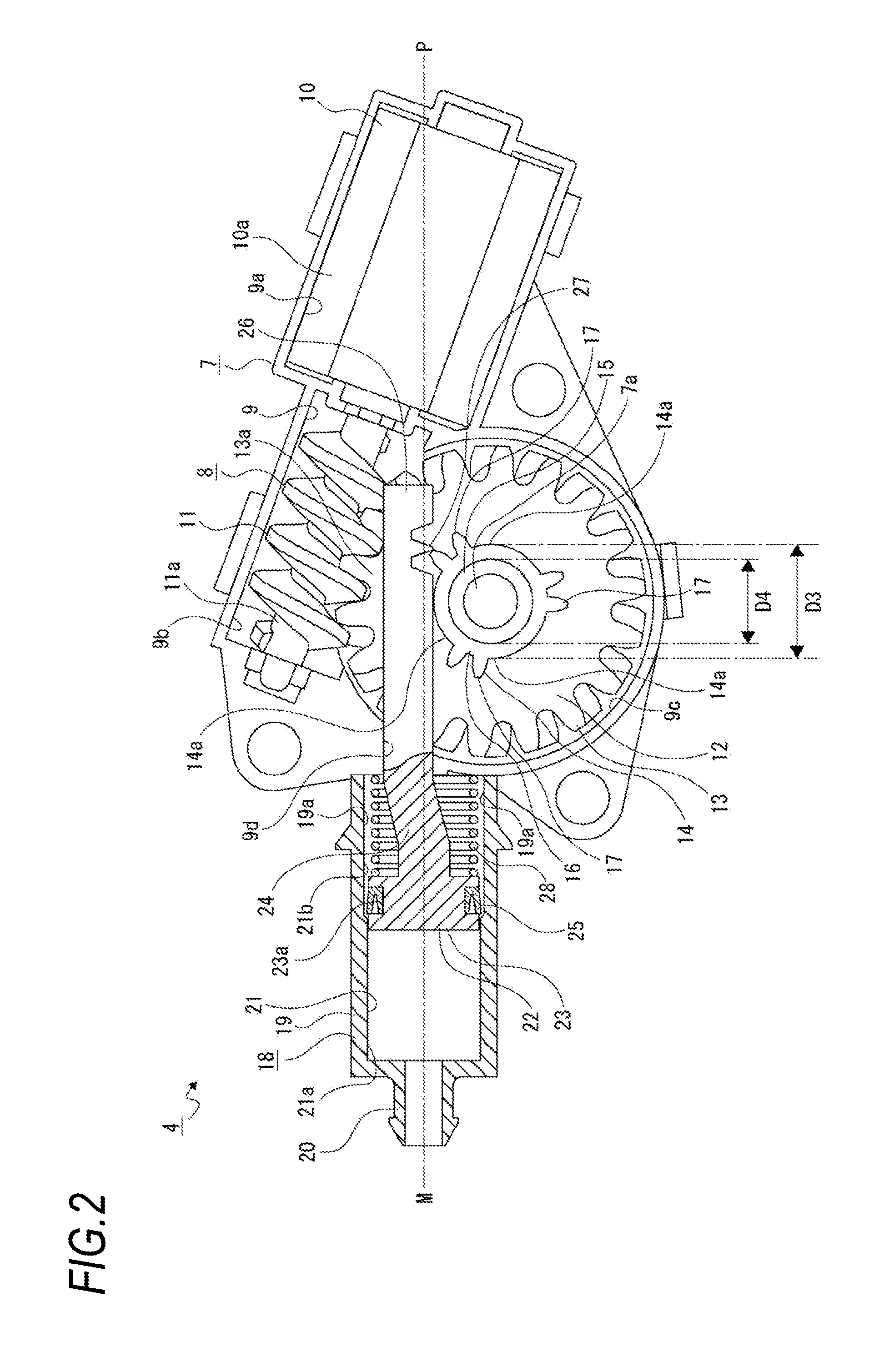
[0059]The foreign material removal device described below includes a cylinder, a pisto


PUM


Abstract

Structural simplification and efficient injection state of high-pressure air from a nozzle are ensured. A foreign material removal device is provided with: a cylinder (18) into which air is caused to flow; a piston (22) which is movably supported in the cylinder and feeds the air introduced into the cylinder in a feeding direction as high-pressure air; and a nozzle (6) which injects the high-pressure air fed by the piston. Thus, the piston is moved relative to the cylinder, the high-pressure air is fed from the cylinder, and the high-pressure air is injected from the nozzle, whereby structural simplification and an efficient injection state of the high-pressure air from the nozzle can be ensured.

Description


Claims


Application Information

Patent Timeline
Owner KOITO MFG CO LTD
Why Eureka
Try Eureka