Simulated Organ Device

Inactive Publication Date: 2017-02-02
SEIKO EPSON CORP
View PDF1 Cites 4 Cited by
  • Summary
  • Abstract
  • Description
  • Claims
  • Application Information

AI Technical Summary

Benefits of technology

[0049]According to the simulated organ device 500 configured as described above, the hydraulic pressure adjustment mechanism 520 adjusts the pressure of the liquid inside the simulated blood vessel 514. Accordingly, adhesion between the simulated parenchyma 512 and the simulated blood vessel 514 varies. Therefore, the simulated organ device according to the embodiment can adjust the adhesion between the simulated parenchyma 512 and the simulated blood vessel 514. As a result, the simulated blood vessel 514 can be stably held inside the simulated parenchyma 512. In particular, in the simulated organ device 500 according to the embodiment, the length of the region A3 having the sealed liquid in the second extra-parenchyma duct line section 514c is changed by the hydraulic pressure adjustment mechanism 520. In this manner, the pressure of the liquid inside the simulated blood vessel 514 is adjusted, and the adhesion between the simulated parenchyma 512 and the simulated blood vessel 514 is changed. Therefore, the simulated organ device 500 according to the embodiment can easily adjust the adhesion between the simulated parenchyma 512 and the simulated blood vessel 514.
[0050]In addition, according to the simulated organ device 500, since the pressure of the liquid inside the simulated blood vessel 514 is adjusted, it is possible to easily test the influence such as blood vessel damage caused by an internal pressure difference.
[0051]FIG. 7 is a view for describing a simulated organ device 600 according to a second embodiment. Compared to the simulated organ device 500 according to the first embodiment, the simulated organ device 600 according to the second embodiment adopts a different configuration which includes a plurality of simulated blood vessels 614A, 614B, and 614C, and a plurality of hydraulic pressure adjustment mechanisms 620A, 620B, and 620C.
[0052]The respective simulated blood vessels 614A, 614B, and 614C are the same as the simulated blood vessel 514 according to the first embodiment, and the respective hydraulic pressure adjustment mechanisms 620A, 620B, and 620C are the same as the hydraulic pressure adjustment mechanism 520 according to the first embodiment. Similarly to the first embodiment, one end side of the respective simulated blood vessels 614A, 614B, and 614C are sealed with respective sealing materials 630A, 630B, and 630C. Similarly to the first embodiment, the other end side of the respective simulated blood vessels 614A, 614B, and 614C are provided with the respective hydraulic pressure adjustment mechanisms 620A, 620B, and 620C. The remaining configurations in the simulated organ device 600 are the same as those according to the first embodiment.
[0053]Similarly to the first embodiment, the simulated organ device 600 configured as described above can adjust the adhesion between the simulated parenchyma and the simulated blood vessels 614A, 614B, and 614C. In particular, the simulated organ device 600 according to the embodiment can individually adjust the adhesion between each of a plurality of the simulated blood vessels 614A, 614B, and 614C and the simulated parenchyma. In addition, the simulated organ device 600 can align the internal pressure of the simulated blood vessels 614A, 614B, and 614C with each other. Therefore, it is possible to easily test the simulated blood vessels having the same property.
[0054]FIG. 8 is a view for describing a simulated organ device 700 according to a third embodiment. Compared to the simulated organ device 600 according to the second embodiment, the simulated organ device 700 according to the third embodiment has a different configuration in which a plurality of the simulated blood vessels 614A, 614B, and 614C merge into one on the other end side, and in which one hydraulic pressure adjustment mechanism 520 is disposed in the merged portion. The remaining configurations are the same as those according to the second embodiment. The hydraulic pressure adjustment mechanism. 520 is the same as the hydraulic pressure adjustment mechanism 520 according to the first embodiment.

Problems solved by technology

However, as a matter of fact, the related art has not sufficiently studied adjustment for adhesion between the simulated parenchyma and the simulated blood vessel.

Method used


Image

  • Simulated Organ Device
  • Simulated Organ Device
  • Simulated Organ Device

Examples


Example

F. Modification Example

[0064]Without being limited to the respective embodiments, and modification examples thereof, the invention can be implemented according to various configurations within the scope not departing from the gist of the invention. For example, the following modification examples can be adopted.

Example

Modification Example 1

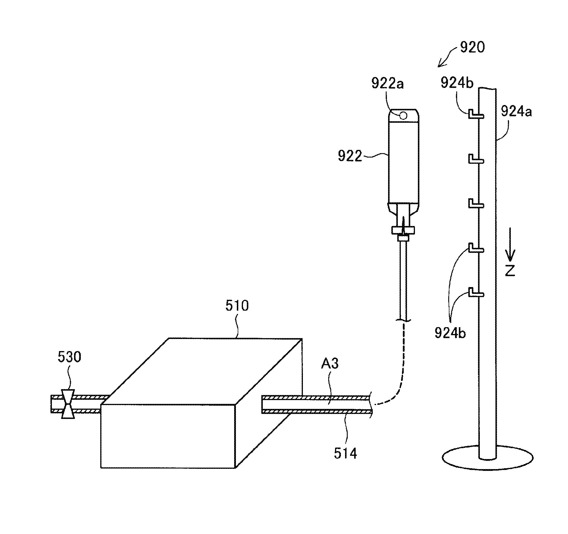
[0065]The respective embodiments and the modification examples adopt a configuration in which both ends of the simulated blood vessel extend to the outside of the support member. In contrast, as a modification example, a configuration may also be adopted in which one end of the simulated blood vessel is installed inside the support member. An end portion on the installed side of the simulated blood vessel is sealed, and the hydraulic pressure adjustment mechanism is disposed on the side extending to the outside. The configuration according to this modification example can also provide an advantageous effect which is the same as that according to the respective embodiments.

Example

Modification Example 2

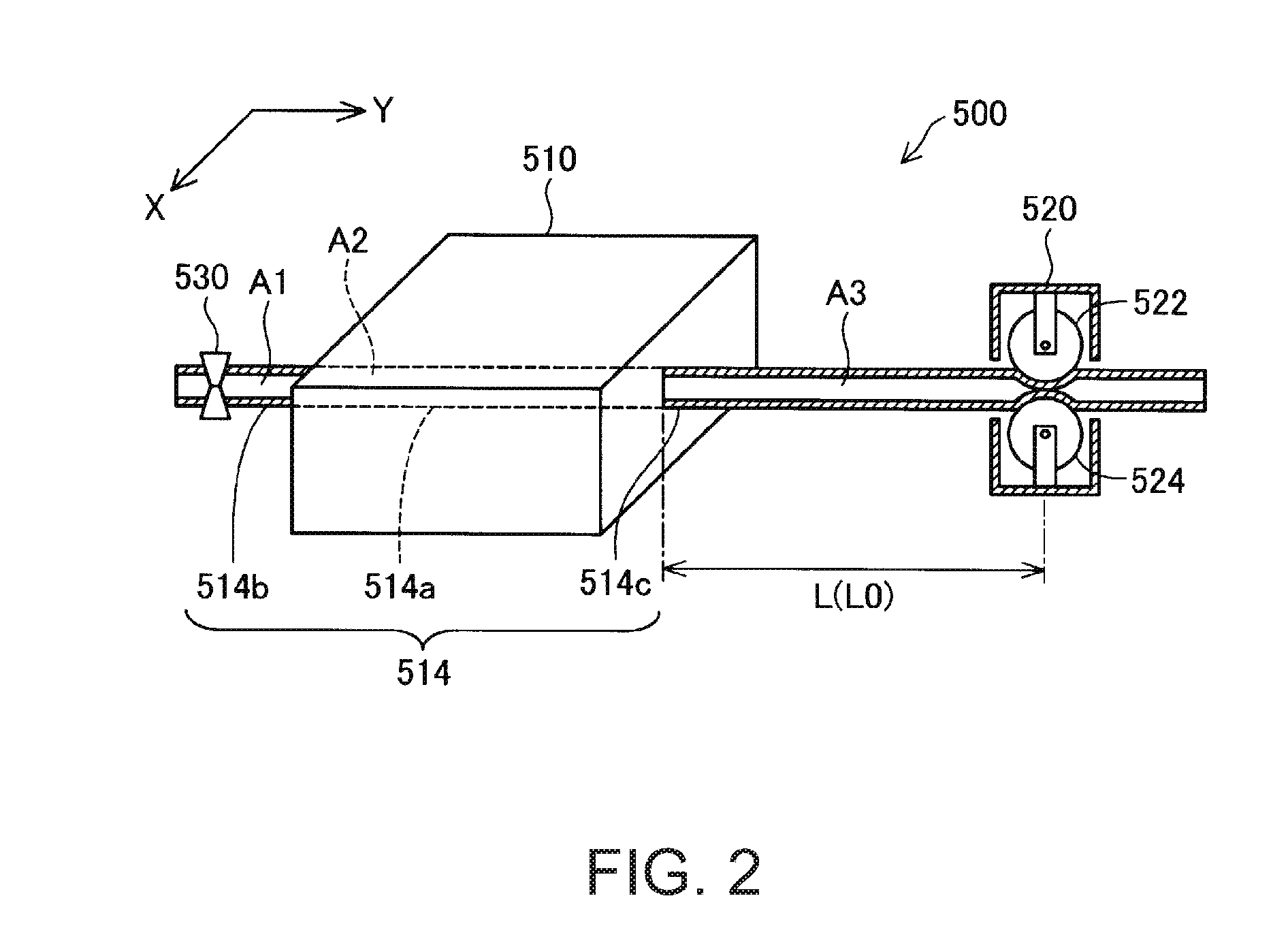
[0066]The first to third embodiments adopt a configuration in which the length of the region A3 having the sealed liquid in the second extra-parenchyma duct line section is changed by a pair of the rollers. However, instead of this configuration, a configuration may also be adopted in which the length is changed by shifting a member having other shapes such as a plate shape and the like. That is, as long as the shape of the simulated blood vessel can be changed, any configuration may be adopted. The configuration according to this modification example can also provide an advantageous effect which is the same as that according to the respective embodiments.


PUM


Abstract

A simulated organ device includes a simulated parenchyma that simulates a parenchyma cell, a simulated blood vessel that accommodates a liquid, and that penetrates the simulated parenchyma, and a hydraulic pressure adjustment unit that can adjust pressure of the liquid accommodated in the simulated blood vessel.

Description


Claims


Application Information

Patent Timeline
Owner SEIKO EPSON CORP
Why Eureka
Try Eureka