Outboard motor mounting structure and outboard motor vessel provided therewith

Active Publication Date: 2017-05-11
YAMAHA MOTOR CO LTD
View PDF2 Cites 1 Cited by
  • Summary
  • Abstract
  • Description
  • Claims
  • Application Information

AI Technical Summary

Benefits of technology

[0037]Another preferred embodiment of the present invention includes an outboard motor vessel including a hull, an outboard motor body, and an outboard motor mounting structure that includes the

Problems solved by technology

A large-sized motor well reduces the strength of a hull structure near its stern, and a large amount of labor and great cost are required to design and produce a hull because the hull structure becomes complicated.
Without being limited

Method used


Image

  • Outboard motor mounting structure and outboard motor vessel provided therewith
  • Outboard motor mounting structure and outboard motor vessel provided therewith
  • Outboard motor mounting structure and outboard motor vessel provided therewith

Examples


Embodiment Construction

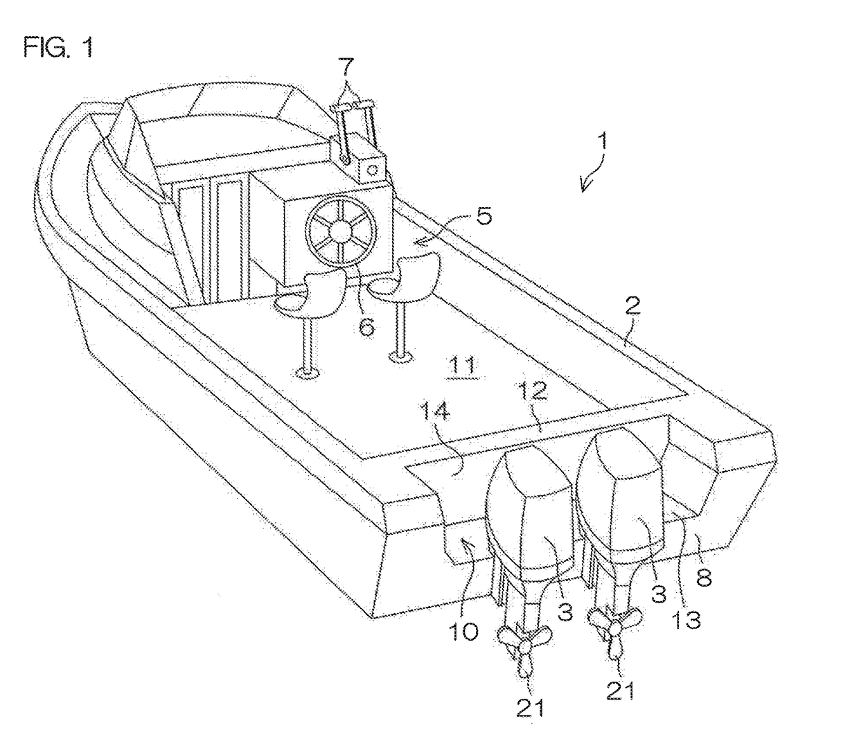
[0050]FIG. 1 is a perspective view of an outboard motor vessel according to a preferred embodiment of the present invention. The outboard motor vessel 1 includes a hull 2 and an outboard motor 3 mounted on the hull 2. In the present preferred embodiment, two outboard motors 3 preferably are arranged on the right and left sides, respectively, and are attached to the stern of the hull 2.

[0051]The hull 2 includes a navigator seat 5 near an intermediate position with respect to a front-rear direction. Operating devices, such as a steering wheel 6 and a shift / throttle lever 7, are disposed at the navigator seat 5. Outboard motors 3 (in the present preferred embodiment, a pair of outboard motors 3) are attached to a stern plate 8 of the hull 2. A motor well 10 is provided in the hull 2 in front of the outboard motors 3. A partition wall 12 that partitions a residence space 11 for the crew is disposed in front of the motor well 10. The motor well 10 is a concave portion having a necessary a


PUM


Abstract

An outboard motor mounting structure mounts an outboard motor body on a hull and includes a mounting bracket fixed to the hull, a swivel bracket joined to the mounting bracket to be tiltable around a tilt axis and that supports the outboard motor body, a flexible connector, and a first connector support that supports the flexible connector at a support position in a region adjacent to the mounting bracket. The relative position of the support position with respect to the mounting bracket does not change depending on a tilt angle of the outboard motor body. The flexible connector includes at least one of a wire, an operating cable, and a pipe that connects equipment on the hull and equipment provided in the outboard motor body. The adjacent region is a region defined between an upper surface of the hull and the engine cover and between a lowest point of the engine cover and the tilt axis in a state that the outboard motor body is tilted up at a maximum tilt angle.

Description


Claims


Application Information

Patent Timeline
Owner YAMAHA MOTOR CO LTD
Why Eureka
Try Eureka