Light source device
a light source and light source technology, applied in the direction of instruments, planar/plate-like light guides, mechanical devices, etc., can solve the problems of color unevenness and difficulty in obtaining uniform light emission in the plane, and achieve the effect of suppressing color unevenness
- Summary
- Abstract
- Description
- Claims
- Application Information
AI Technical Summary
Benefits of technology
Problems solved by technology
Method used
Image

Examples
first embodiment
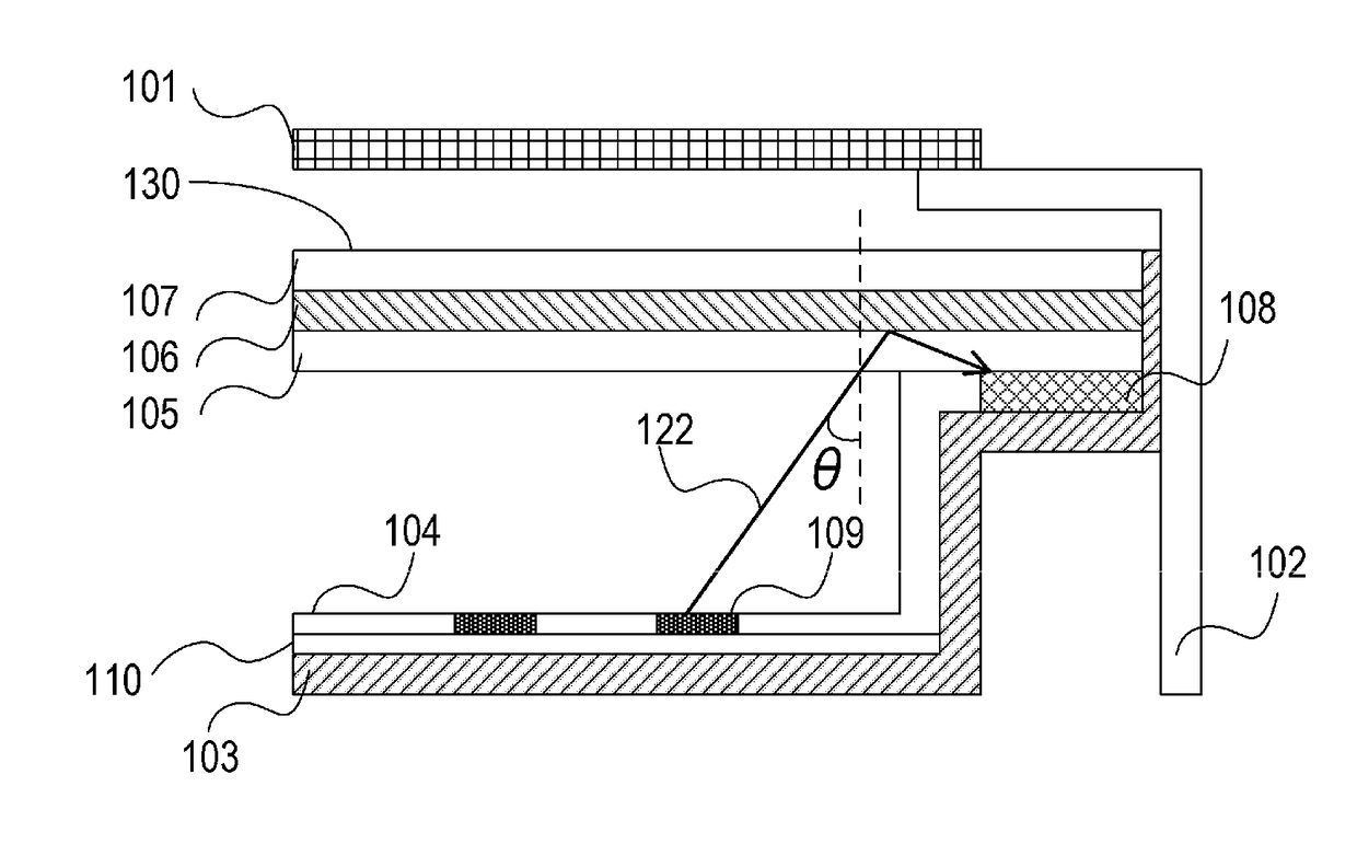
[0025]A light source device according to a first embodiment of the present invention is explained. The light source device according to this embodiment can be used, for example, as a light source device of an image display apparatus including a display unit that transmits light from the light source device to display an image on a screen. Specifically, the light source device according to this embodiment can be used as light source devices of imagedisplay apparatuses such as a liquid crystal display apparatus, an advertisement display apparatus, and a sign display apparatus. The light source device according to this embodiment can also be used as a light source device of an image display apparatus including a display element (e.g., a micro electro mechanical system (MEMS) shutter) different from a liquid crystal element of the liquid crystal display apparatus. The light source device according to this embodiment can also be used as light source devices of apparatuses (a room light, a s
second embodiment
[0045]A light source device according to a second embodiment of the present invention is explained below. In this embodiment, a configuration is explained in which unevenness is provided at an end portion of a light source holding member 103 in order to retain positions of a wavelength conversion member and the like in a plane of a sheet member.
[0046]FIG. 3A is a diagram (a top view) showing an example of the configuration of a liquid crystal display apparatus 200 according to this embodiment. FIG. 3B is an A-A′ sectional view of FIG. 3A. A B-B′ cross section of FIG. 3A is the same as FIG. 1.
[0047]The liquid crystal display apparatus 200 includes a liquid crystal panel 201, a liquid crystal panel holding member 202, and the light source device. The light source device includes a light source holding member 203, a reflecting member 204, a diffusing member 205, a wavelength conversion member 206, a beam control member 207, a light absorbing member 208, light sources 209, a light source b
third embodiment
[0064]In this embodiment, the configuration of a light source device in the case in which a fixing member is used to fix the diffusing member 105 and the like to the light source holding member 103 is explained.
[0065]FIG. 4A is a diagram (a top view) showing an example of the configuration of a liquid crystal display apparatus 300 according to this embodiment. FIG. 4B is a C-C′ sectional view of FIG. 4A.
[0066]The liquid crystal display apparatus 300 includes a liquid crystal panel 301, a liquid crystal panel holding member 302, and the light source device. The light source device includes a light source holding member 303, a reflecting member 304, a diffusing member 305, a wavelength conversion member 306, a beam control member 307, a light absorbing member 308, a light source 309, a light source board 310, and a sheet fixing member 311.
[0067]The liquid crystal panel 301 is a member same as the liquid crystal panel 101 in the first embodiment (FIG. 1).
[0068]The liquid crystal panel hol
PUM
 Abstract
Description
Claims
Application Information
 - R&D Engineer
- R&D Manager
- IP Professional
- Industry Leading Data Capabilities
- Powerful AI technology
- Patent DNA Extraction
Browse by: Latest US Patents, China's latest patents, Technical Efficacy Thesaurus, Application Domain, Technology Topic.
© 2024 PatSnap. All rights reserved.Legal|Privacy policy|Modern Slavery Act Transparency Statement|Sitemap