External Gear Pump Integrated with Two Independently Driven Prime Movers

a prime movers and external gear technology, applied in the direction of machines/engines, rotary/oscillating piston pump components, liquid fuel engines, etc., can solve the problems of affecting sheared materials are known to be detrimental to the functionality of the system, and the system can be particularly troublesome. to achieve the effect of reducing or eliminating the problem of contamination

Active Publication Date: 2017-07-20
PROJECT PHOENIX
View PDF0 Cites 9 Cited by
  • Summary
  • Abstract
  • Description
  • Claims
  • Application Information

AI Technical Summary

Benefits of technology

This patent describes a system for delivering fluids through a pump. It uses two different types of fluid sources: one contains liquids and another does not contain them. These fluids move together within the pump's housing. When these fluids reach their destination, they work like a single unit. They use separate motors to control both the movement and operation of the fluids. By doing this, there is no problem with contaminating existing systems.

Problems solved by technology

The technical problem addressed in this patent is how to improve the performance and reliability of gear pumps in industrial applications where high pressure and flow rates occur, while reducing contaminants and maintaining cleanliness.

Method used


Image

  • External Gear Pump Integrated with Two Independently Driven Prime Movers
  • External Gear Pump Integrated with Two Independently Driven Prime Movers
  • External Gear Pump Integrated with Two Independently Driven Prime Movers

Examples


Embodiment Construction

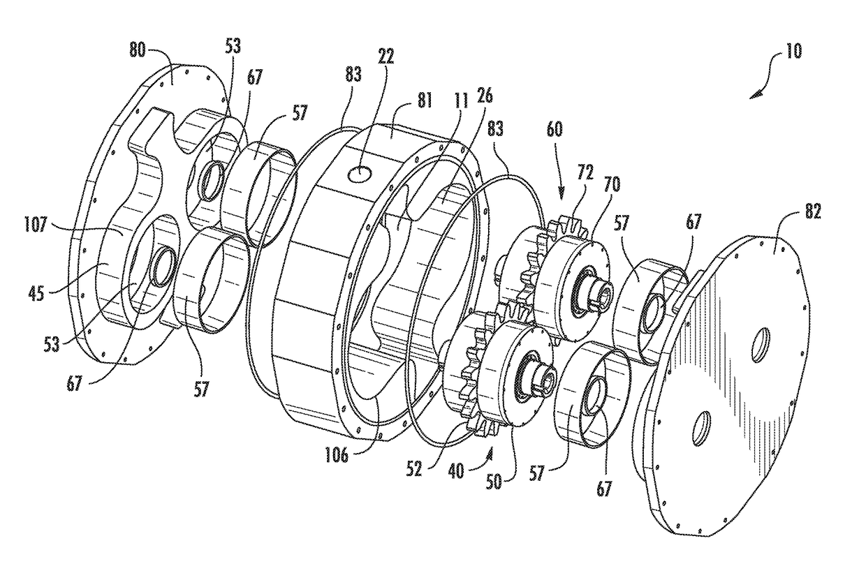
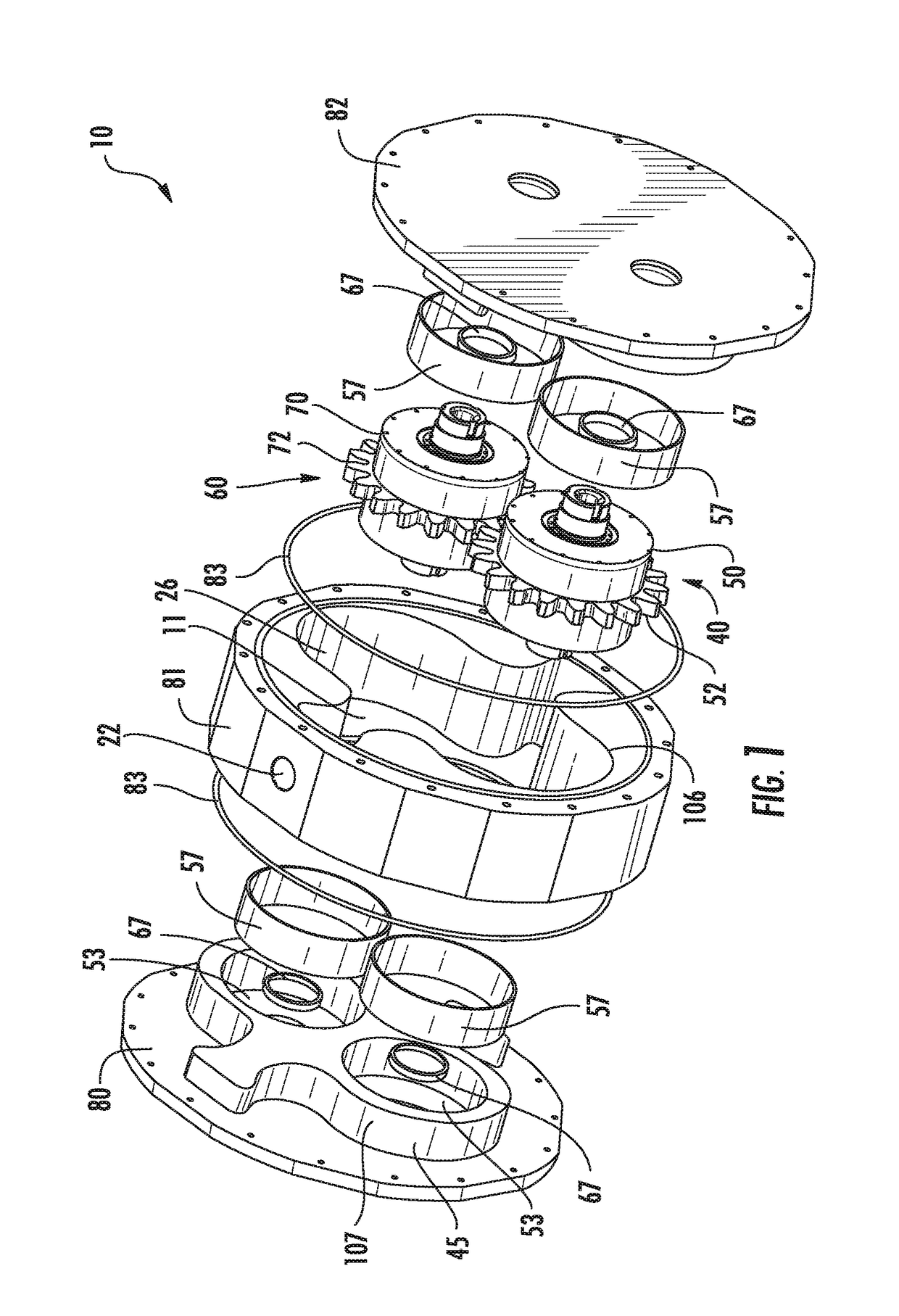
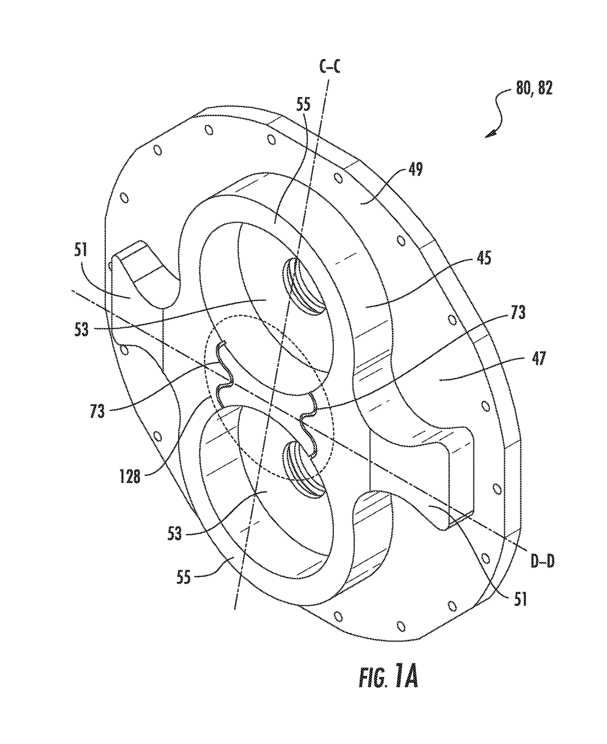
[0036]Exemplary embodiments of the present invention are directed to a pump with independently driven fluid drivers disposed between two self-aligning balancing plates that form part of the pump casing. These exemplary embodiments will be described using embodiments in which the pump is an external gear pump with two prime movers, the prime movers are electric motors and the fluid displacement members are external spur gears with gear teeth. However, those skilled in the art will readily recognize that the concepts, functions, and features described below with respect to electric-motor-driven external gear pump with two fluid drivers can be readily adapted to external gear pumps with other gear designs (helical gears, herringbone gears, or other gear teeth designs that can be adapted to drive fluid), to prime movers other than electric motors, e.g., hydraulic motors or other fluid-driven motors, or other similar devices that can drive a fluid displacement member, and to fluid displacem


PUM


Abstract

A pump includes a casing defining an interior volume. The pump casing includes at least one balancing plate that can be part of a wall of the pump casing with each balancing plate including a protruding portion having two recesses. Each recess is configured to accept one end of a fluid driver. The balancing plate aligns the fluid displacement members with respect to each other such that the fluid displacement members can pump the fluid when rotated. The balancing plates can include cooling grooves connecting the respective recesses. The cooling grooves ensure that some of the liquid being transferred in the internal volume is directed to bearings disposed in the recesses as the fluid drivers rotate.

Description


Claims


Application Information

Patent Timeline
Owner PROJECT PHOENIX
Why Eureka
Try Eureka