Excavator hydraulic control system and method

A hydraulic control system, hydraulic system technology, applied in mechanical equipment, fluid pressure actuating devices, servo motors, etc., can solve the problems of energy loss, large energy loss, poor economy, etc., and achieve the effect of solving energy loss

Active Publication Date: 2021-05-11
济宁海推重工机械股份有限公司
View PDF6 Cites 0 Cited by
  • Summary
  • Abstract
  • Description
  • Claims
  • Application Information

AI Technical Summary

Benefits of technology

The technical purpose described by this patented technology relates to an improved way for controlling fluid flow during construction operations without causing excessive pressure or over-pressure issues caused by traditional methods like relief valves.

Problems solved by technology

This patented problem addressed in this patents relates to improving an existing wheelchair excavators' performance without sacrificing their cost or power consumption compared to current systems.

Method used


Image

  • Excavator hydraulic control system and method
  • Excavator hydraulic control system and method
  • Excavator hydraulic control system and method

Examples


Embodiment 1

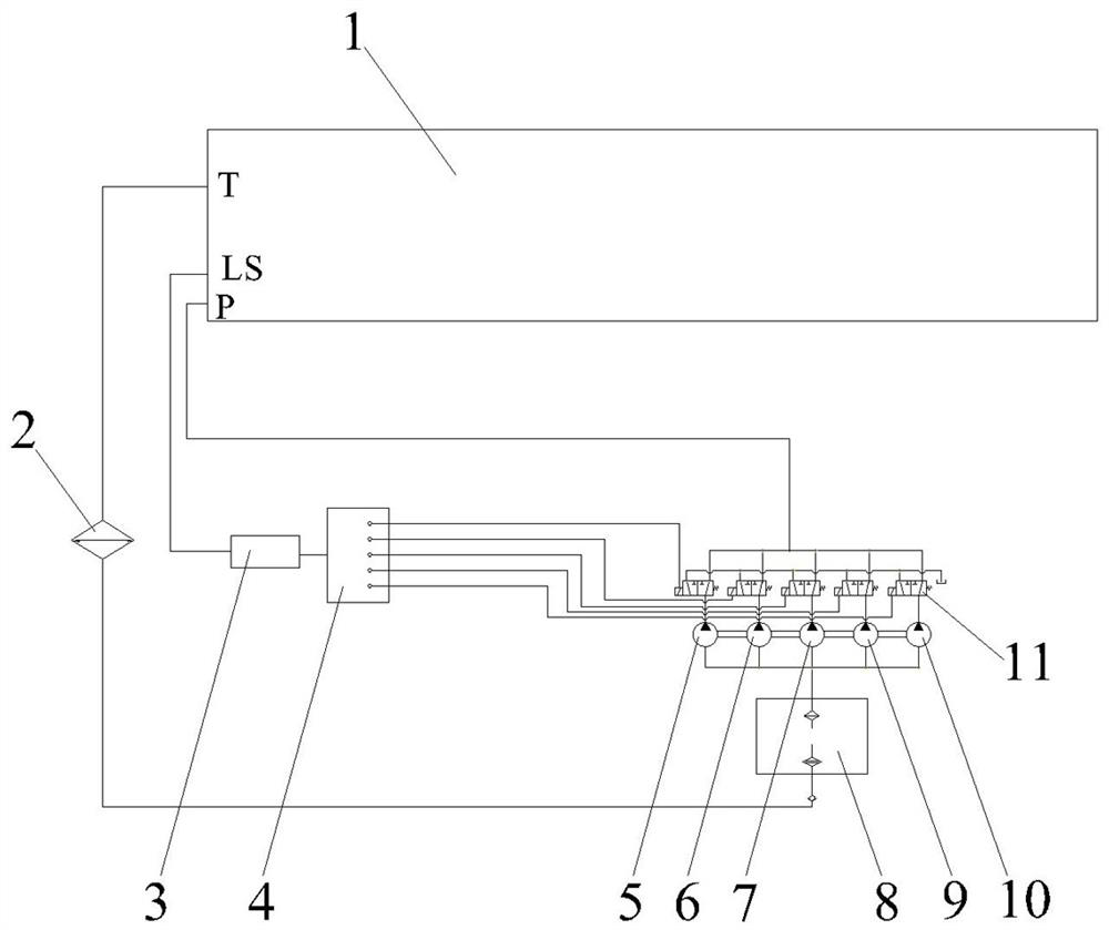
[0040]A hydraulic control system for an excavator, comprising a LUDV load sensing valve 1, a control unit 4, a hydraulic oil tank 8, a preset number of gear pumps, and a two-position three-way electric control valve corresponding to the gear pumps one by one; the two-position three-way The oil inlet port of the electric control valve is connected to the oil outlet port of the corresponding gear pump, and the two oil outlet ports of the two-position three-way electric control valve are respectively connected to the oil inlet port of the LUDV load sensing valve and the system return port. The oil circuit (that is, connected to the hydraulic oil tank), each two-position three-way electric control valve is respectively connected with the control unit, the LS hole of the LUDV load sensing valve is connected with a pressure sensor 3, and the pressure sensor 3 is connected with the control unit 4, The control unit 4 controls the two-position three-way electric control valve in three stag

Embodiment 2

[0070] A hydraulic control method for an excavator, in which a LUDV load sensing valve, a control unit, a preset number of gear pumps, and two-position three-way electric control valves corresponding to the gear pumps are set in the hydraulic system; the two-position three-way electric control valve The oil inlet of the control valve is connected to the oil outlet of the corresponding gear pump, and the two oil outlets of the two-position three-way electric control valve are respectively connected to the oil inlet of the LUDV load sensing valve and the oil return of the system. Each two-position three-way electric control valve is connected to the control unit, and the LS hole of the LUDV load sensing valve is connected to a pressure sensor, which is connected to the control unit. The control unit controls the two-position three-way Electric control valve for control:

[0071] Stage I: From the initial working of the hydraulic system until the pressure detected by the pressure se


PUM


Abstract

An excavator hydraulic control system and method, relating to the technical field of excavator hydraulic control, including a LUDV load sensing valve, a control unit, a preset number of gear pumps, and two-position three-way electric control valves corresponding to the gear pumps one by one; The oil inlet of the two-position three-way electric control valve is connected to the oil outlet of the corresponding gear pump, and the two oil outlets of the two-position three-way electric control valve are respectively connected to the oil inlet of the LUDV load sensing valve. Each two-position three-way electric control valve is respectively connected to the control unit. The LS port of the LUDV load sensing valve is connected to a pressure sensor, and the pressure sensor is connected to the control unit. The control unit is divided into three The two-position three-way electric control valve is controlled in two stages. This excavator hydraulic control system and method have different flow rates under different pressures, thus solving the problem of energy loss due to the overflow of the overflow valve in the traditional excavator hydraulic control system and method. The problem.

Description


Claims


Application Information

Patent Timeline
Owner 济宁海推重工机械股份有限公司
Why Eureka
Try Eureka