Information inputting apparatus and image forming apparatus having information inputting apparatus
- Summary
- Abstract
- Description
- Claims
- Application Information
AI Technical Summary
Benefits of technology
Problems solved by technology
Method used
Image

Examples
Example
First Modified Embodiment
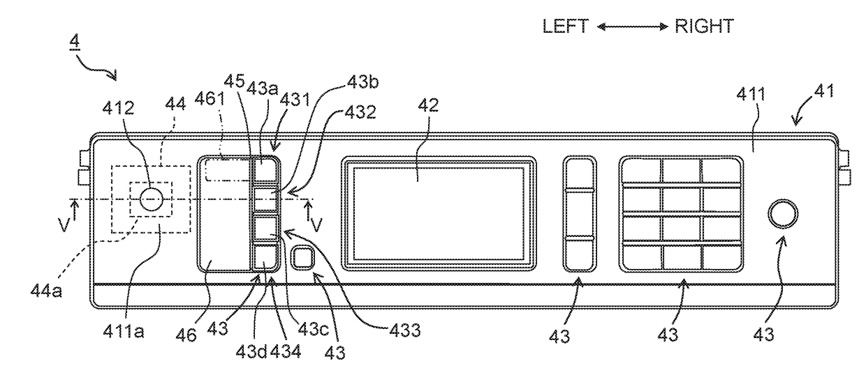
[0044]A panel unit 7 depicted in FIG. 6 according to a first modified embodiment is different from the above embodiment in that the panel unit 7 includes an auxiliary rib 71 as an exemplary auxiliary protrusion. Other configurations except the auxiliary rib 71 are the same as those of the above embodiment, and thus any explanation therefor will be omitted.
[0045]The auxiliary rib 71, which is the auxiliary protrusion provided on the opposite side of the rib 45 across the first to fourth push buttons 431 to 434, is formed integrally with the panel 411. The auxiliary rib 71 has a height at least equal to or higher than the height, of the operation surface 43a to 43d of the first to fourth push buttons 431 to 434, at which the buttons react by being pushed. The auxiliary rib 71 is a single member extending linearly on the right side of the first to fourth push buttons 431 to 434 in the direction orthogonal to the left-right direction.
[0046]The user may put the info
Example
Second Modified Embodiment
[0047]A panel unit 8 depicted in FIG. 7 according to a second modified embodiment is different from the above embodiment in that the panel unit 8 includes four bosses 81 as an exemplary protrusion. Other configurations except the bosses 81 are the same as those of the above embodiment, and thus any explanation therefor will be omitted.
[0048]Each of the bosses 81, which is a substantially cylindrical protrusion, is provided on the left of the corresponding one of the first to fourth push buttons 431 to 434. The height of the bosses 81 is the same as that of the rib 45. It is only required that the bosses 81 be provided between the placement surface 411a and the first to fourth push buttons 431 to 434. The number of bosses 81 may be at least one, two or three, or five or more.
[0049]As with the above embodiment, when the user puts the information terminal P on the placement surface 411a, the bosses 81 may prevent the surface of the information terminal P on the p
PUM
 Abstract
Description
Claims
Application Information
 - R&D Engineer
- R&D Manager
- IP Professional
- Industry Leading Data Capabilities
- Powerful AI technology
- Patent DNA Extraction
Browse by: Latest US Patents, China's latest patents, Technical Efficacy Thesaurus, Application Domain, Technology Topic.
© 2024 PatSnap. All rights reserved.Legal|Privacy policy|Modern Slavery Act Transparency Statement|Sitemap