Input device, wearable terminal, mobile terminal, method of controlling input device, and control program for controlling operation of input device
a technology of input device and control program, which is applied in the field of input device, wearable terminal, mobile terminal, and control program for controlling the operation of input device, can solve the problems of large improvement of gui (graphical user interface) operability, and achieve the effect of improving operability
- Summary
- Abstract
- Description
- Claims
- Application Information
AI Technical Summary
Benefits of technology
Problems solved by technology
Method used
Image

Examples
embodiment 1
ample 1 for Terminal Device 10
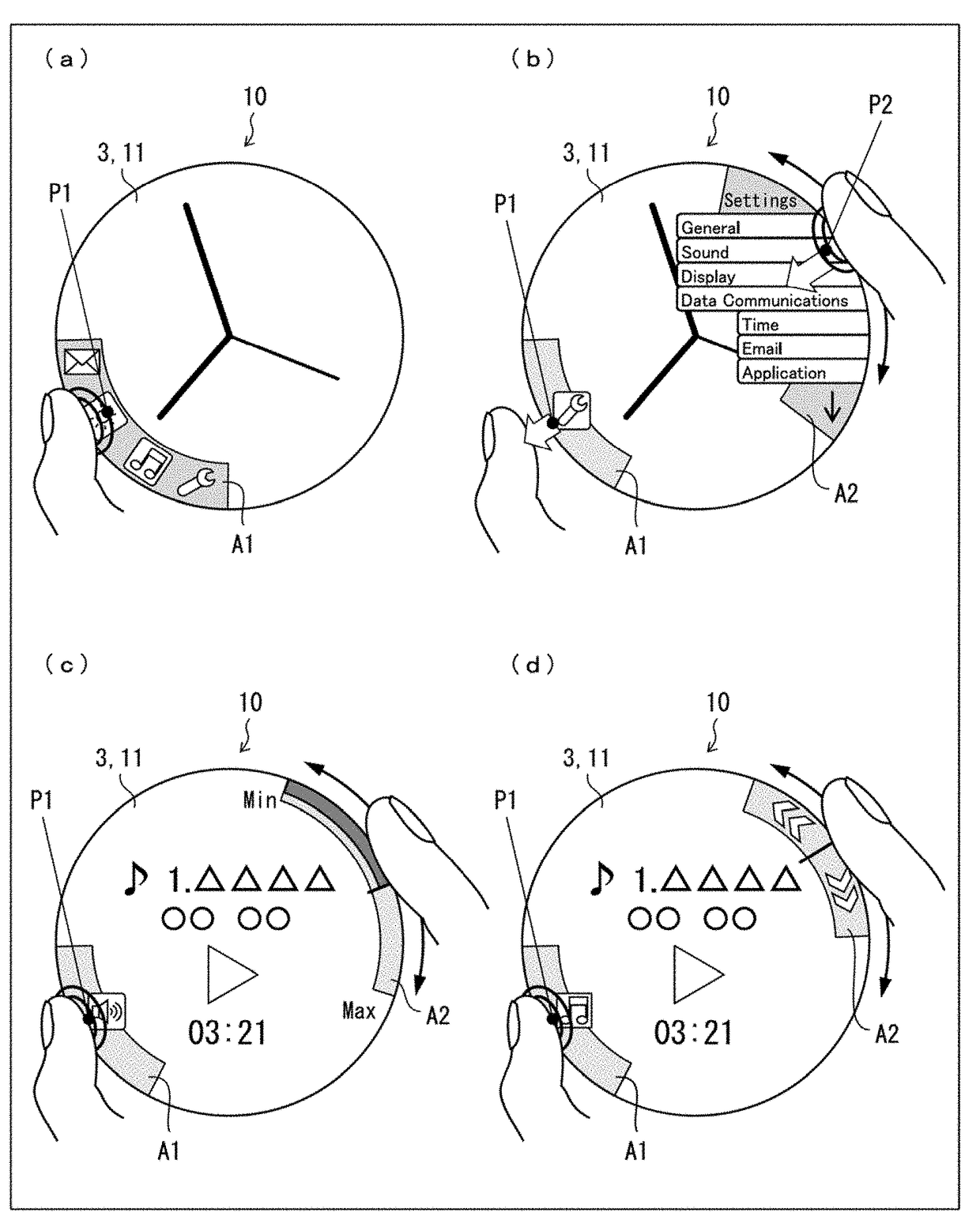
[0065]Operation examples for the terminal device 10 in accordance with Embodiment 1 will be described in reference to FIG. 5. Portions (a) and (b) of FIG. 5 show an example of basic touch operations on an edge of the screen or side faces of the casing of the terminal device 10. The user can select a menu item from a menu displayed on a peripheral part of the screen or operate the menu by a combination of these basic touch operations.
[0066]Portions (a) and (b) of FIG. 5 show an operation example in which the user can select one of items for operation from a displayed menu. In an example of selecting an item from a main menu displayed in the area A1 shown in portion (a) of FIG. 5, if the user selects a main menu item by, for example, a “single tapping (brief touch and release)” or a “press and hold” in the contact position P1 with the thumb, an associated submenu is displayed in the area A2 as shown in portion (b) of FIG. 5 by using the position opposite fro
embodiment 2
ample 2 for Terminal Device 10
[0073]Operation examples for the terminal device 10 in accordance with Embodiment 2 will be described in reference to FIGS. 6 to 8. FIG. 6 shows an operation example of a music player application. Portion (a) of FIG. 6 shows the terminal device 10 displaying a main menu near the first touch position. Portion (a) of FIG. 6 shows a mode in which, for example, “Play Menu,”“Select Song,” and “Volume” icons are displayed as part of a main menu near the lower left side of the display unit 3 on the paper showing the figure and when touched, respectively invoke associated submenus across from the main menu.
[0074]Portion (b) of FIG. 6 shows the terminal device 10 either displaying the “Play Menu” or responding to the user's subsequent actions. The “Play Menu” includes “Pause” and “Fast Forward / Rewind” icons (buttons or menu items). To fast forward / rewind, the user slides the finger starting at the first touch position and moving in the directions indicated by a
embodiment 3
ample 3 for Terminal Device 10
[0084]Operation examples for the terminal device 10 in accordance with Embodiment 3 will be described in reference to FIGS. 9 to 13. FIG. 9 shows an operation example of an email or other text (Japanese language) input application. Portion (a) of FIG. 9 shows the terminal device 10 displaying an initial screen (vowel keys). Portion (b) of FIG. 9 shows the terminal device 10 displaying a text input screen or responding to the user's subsequent actions. Portion (c) of FIG. 9 shows the terminal device 10 displaying a list of addresses or responding to the user's subsequent actions.
[0085]Portions (a) and (b) of FIG. 9 show an exemplary mode of text input operation. Vowels are displayed in the first touch position (edge; contact position P1 in the area A1). If the user selects a character, for example “”, by touching on the character, candidate characters (candidate consonants or menu items) belonging to the column starting with “” are displayed in the area A2
PUM
 Abstract
Description
Claims
Application Information
 - R&D Engineer
- R&D Manager
- IP Professional
- Industry Leading Data Capabilities
- Powerful AI technology
- Patent DNA Extraction
Browse by: Latest US Patents, China's latest patents, Technical Efficacy Thesaurus, Application Domain, Technology Topic.
© 2024 PatSnap. All rights reserved.Legal|Privacy policy|Modern Slavery Act Transparency Statement|Sitemap