Glass laminate with pane having glass-glass laminate structure
- Summary
- Abstract
- Description
- Claims
- Application Information
AI Technical Summary
Problems solved by technology
Method used
Image

Examples
Example
Example 1
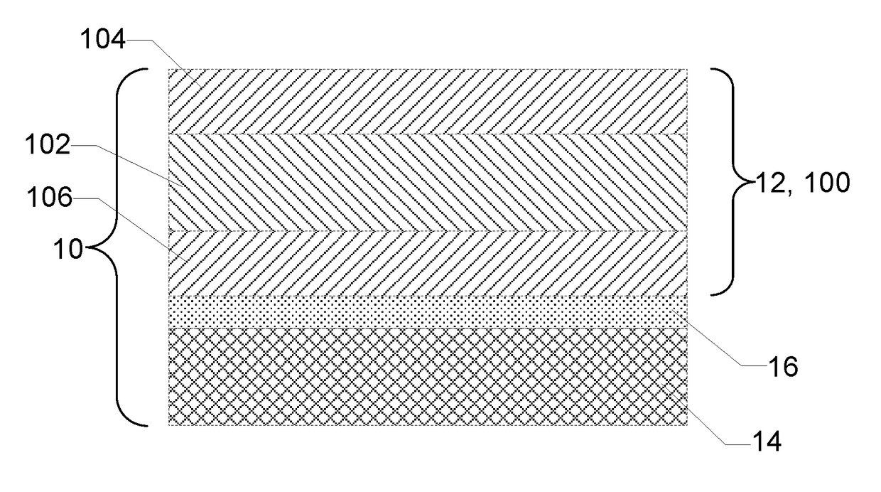
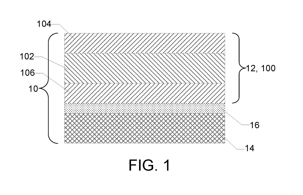
[0102]A glass laminate similar to that shown in FIG. 1 was formed. The first pane was a glass-glass laminate structure with a thickness of about 1 mm. The ratio of the core layer thickness to the cladding layer thickness (the sum of the thicknesses of both cladding layers) was about 6. The compressive stress of the cladding layers was about 150 MPa, and the central tension of the core layer was about 25 MPa. The interlayer was formed from PVB and had a thickness of about 0.8 mm. The second pane was a chemically strengthened glass sheet with a thickness of about 0.4 mm.
[0103]The glass laminate was positioned at an angle of about 30° from vertical, and the first pane of the glass laminate was struck with 12 oz of SAE G699 gravel dropped a few pieces at a time from a height of about 6 ft. 8 out of 8 samples of the glass laminate that were tested survived the impact.
Example
Example 2
[0104]A glass laminate similar to that shown in FIG. 1 was formed. The first pane was a glass-glass laminate structure with a thickness of about 1 mm. The ratio of the core layer thickness to the cladding layer thickness (the sum of the thicknesses of both cladding layers) was about 9. The compressive stress of the cladding layers was about 190 MPa, and the central tension of the core layer was about 21 MPa. The interlayer was formed from PVB and had a thickness of about 0.8 mm. The second pane was a chemically strengthened glass sheet with a thickness of about 0.4 mm.
[0105]The glass laminate was positioned at an angle of about 30° from vertical, and the first pane of the glass laminate was struck with 12 oz of SAE G699 gravel dropped a few pieces at a time from a height of about 6 ft. 8 out of 8 samples of the glass laminate that were tested survived the impact.
Example
Example 3
[0106]A glass laminate is formed. The first pane is a glass-glass laminate structure with a thickness of about 1 mm. The interlayer is formed from PVB and has a thickness of about 0.8 mm. The second pane is a second glass-glass laminate structure with a thickness of about 0.5 mm.
PUM
| Property | Measurement | Unit |
|---|---|---|
| Temperature | aaaaa | aaaaa |
| Temperature | aaaaa | aaaaa |
| Length | aaaaa | aaaaa |
Abstract
Description
Claims
Application Information
 - R&D Engineer
- R&D Manager
- IP Professional
- Industry Leading Data Capabilities
- Powerful AI technology
- Patent DNA Extraction
Browse by: Latest US Patents, China's latest patents, Technical Efficacy Thesaurus, Application Domain, Technology Topic.
© 2024 PatSnap. All rights reserved.Legal|Privacy policy|Modern Slavery Act Transparency Statement|Sitemap