Novel biodegradable and non-biodegradable 3D printed implants as a drug delivery system
- Summary
- Abstract
- Description
- Claims
- Application Information
AI Technical Summary
Benefits of technology
Problems solved by technology
Method used
Image

Examples
example 1
Coating PLA Beads with Antibiotics
[0096]In this example, bioactive 3D printing filaments using gentamicin sulfate, tobramycin, and nitrofurantoin antibiotics were created and a process was developed to coat PLA beads with 1%, 2.5%, and 5% coating of the antibiotics. The coated PLA beads were then extruded into filament usable for FDM 3D printing. The 3D printing material used in the additive coating study were commercially-available PLA beads. To perform the coating process, the antibiotics chosen for testing were gentamicin, tobramycin, and nitrofurantoin, with KJL 705 Silicone Oil as the chemical used to hold the antibiotics to the heads.
[0097]During the coating portion of the experiment, basic chemical measuring devices, test tubes, and sterilization chemicals were required. A vortex machine to ensure complete coating, as well as a mortar and pestle to crush the antibiotics into a uniform powder, were also used. For extrusion process, an Extrusionbot filament extruder turned the PLA
example 2
Total Knee Replacement CAD Development
[0102]Using information gathered on total knee replacement design aspects, bone geometry data provided by Mimics software, and a total knee replacement sample, a total knee replacement three dimensional model was developed in Solidworks. FIG. 5 shows the model iteration. The total knee replacement 1200 includes a femoral component 1201, a tibial component 1203 and a spacer 1202 that is placed in between the femoral and tibial components. The femoral component possesses two lateral surfaces, one on each opposite side 1204 (opposite side not shown), each lateral surface having an outer edge 1205, and inner edge 1206. The outer edge 1205 may be of a shape of semi-wheel configured to be placed on top of the spacer 1202. The inner edge 1206 may be formed by a multiple concatenated straight lines at different lengths. The outer edge and inner edge define the area of the lateral surface.
example 3
Use of Microchannel and Reservoir Network Inside the Orthopedic Implant
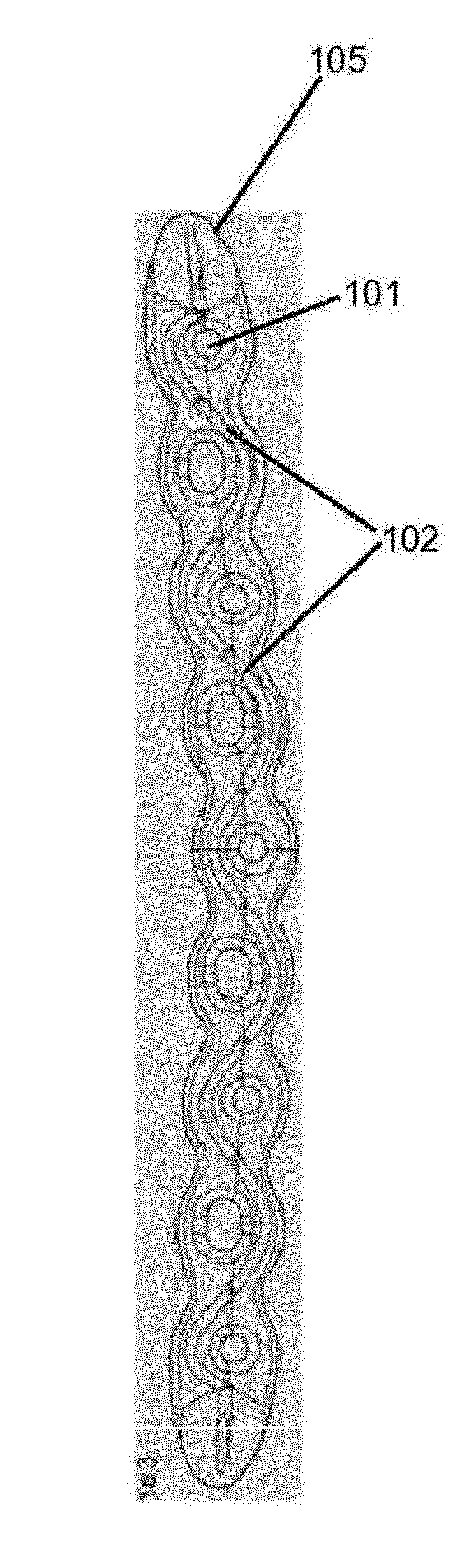
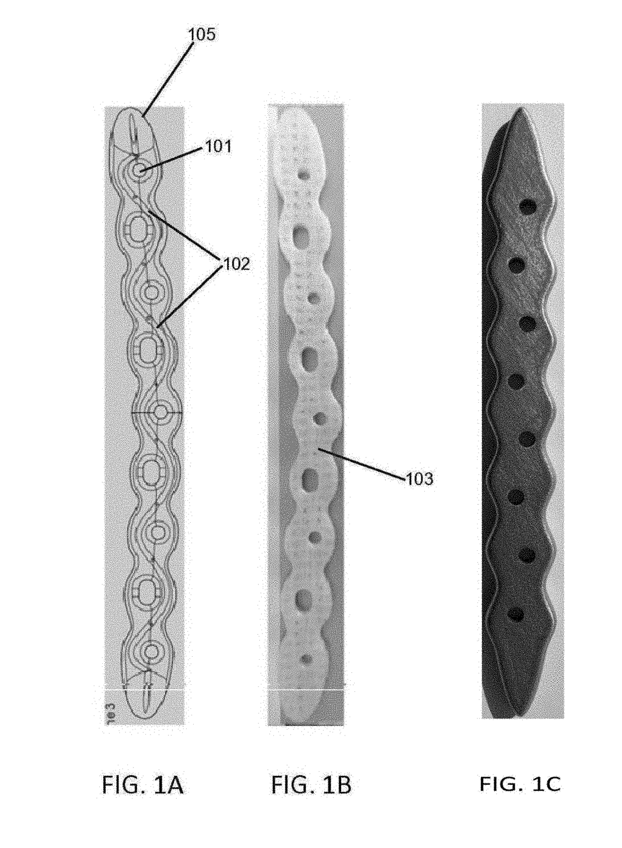
[0103]In this example drug delivery methods were developed for manufacturing a microchannel / reservoir network inside the orthopedic implant, filled with antibiotics, which would then elute through the implant, primarily via diffusion, for the 6-8 week treatment period.
[0104]FIGS. 6A-6D elaborates in at least one such embodiment. In this embodiment, femoral component contain a pair of two reservoirs 602, each reservoir being disposed inside the femoral component proximate to the lateral surface and between the outer edge and inner edge of the surface. Each reservoir form a curve to correspond to the shape of the outer or inner and is connected to two microchannels 601, 606, to facility drug delivery, one of which, 601, is connected to the reservoir at approximate a mid-segment point of the reservoir and extends outward perpendicular to and outside the lateral surface. In this example, the other microchannel 606 is
PUM
| Property | Measurement | Unit |
|---|---|---|
| Fraction | aaaaa | aaaaa |
| Fraction | aaaaa | aaaaa |
| Diameter | aaaaa | aaaaa |
Abstract
Description
Claims
Application Information
 - R&D Engineer
- R&D Manager
- IP Professional
- Industry Leading Data Capabilities
- Powerful AI technology
- Patent DNA Extraction
Browse by: Latest US Patents, China's latest patents, Technical Efficacy Thesaurus, Application Domain, Technology Topic.
© 2024 PatSnap. All rights reserved.Legal|Privacy policy|Modern Slavery Act Transparency Statement|Sitemap