Adaptive turn-off delay time compensation for LED controller

a technology of led controllers and turn-off delays, which is applied in the direction of electroluminescent light sources, electric lighting sources, and use of semiconductors. it can solve the problems of long ton_delay, inability to adjust the turn-on and turn-off times of led controllers, and inability to adjust the turn-off tim

Active Publication Date: 2018-07-05
TEXAS INSTR INC
View PDF12 Cites 4 Cited by
  • Summary
  • Abstract
  • Description
  • Claims
  • Application Information

AI Technical Summary

Benefits of technology

[0013]An integrated circuit comprises a clock signal input pin; a pulse width modulated signal input pin; a gate drive signal output pin; and a sense input pin. The integrated circuit is coupled to a series connection between a power lead supplying a voltage and a field ground lead...

Problems solved by technology

Although the controlling pulse width modulated signal may have a well-defined 50% duty cycle of on and off times, unequal capacitances in the circuits implementing the flow of current through the LEDs may cause unequal turn on and turn off times of the current, and produce other than a 50% duty cycle of the LEDs.
In these applications, a problem exists in turning the current Iled t...

Method used


Image

  • Adaptive turn-off delay time compensation for LED controller
  • Adaptive turn-off delay time compensation for LED controller
  • Adaptive turn-off delay time compensation for LED controller

Examples


Embodiment Construction

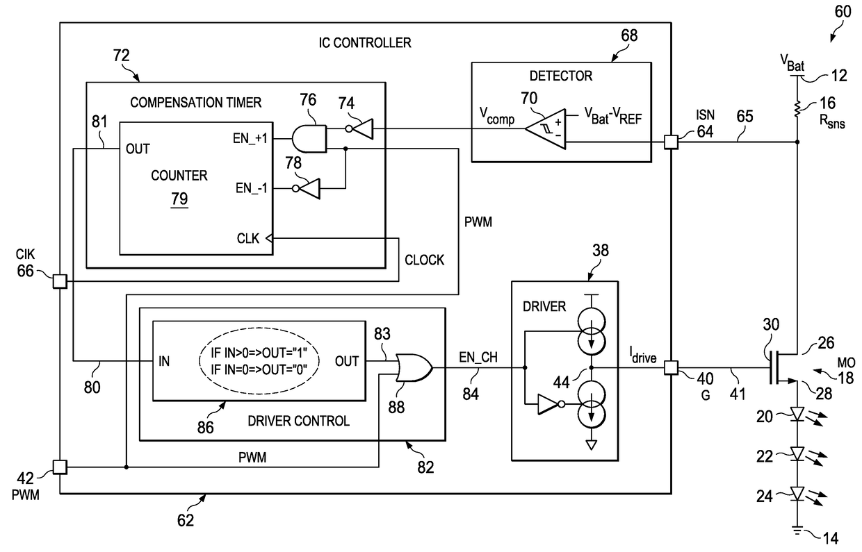
[0019]In FIG. 3, circuit 60 includes the series connection between the power lead 12 and the field ground lead 14 of the current sense resistor 16 acting as a sense resistor Rsns, the power field effect transistor (FET) 18, and the three LEDs 20, 22, and 24. Circuit 60 also includes an integrated circuit controller 62.

[0020]Controller 62 has the Idrive or gate output pin 40, the PWM signal input pin 42, an Isn sense input pin 64 connected by an external lead 65 to between the resistor 16 and drain 26 of transistor 18, a clock input pin 66, and switching circuit 44 having an output connected to the Idrive pin 40.

[0021]A detector circuit 68 includes a comparator having a non-inverting input connected to a reference voltage Vbat-Vref, an inverting input connected to the Isn sense pin 64, and a Vcomp output.

[0022]A compensation timer circuit 72 includes an inverter 74 having an input connected to the Vcomp output of the comparator 70 and an output. An AND gate 76 has an input connected ...


PUM


Abstract

A light emitting diode controller integrated circuit includes counter circuitry having inputs coupled to a clock signal input pin, a pulse width modulated signal input pin, and a sense input pin, and has a count output coupled to a gate drive signal output to an external power transistor. The power transistor is connected in series between a power lead, a sense resistor, and a light emitting diode. The sense input pin is coupled to the series connection between the resistor and the transistor. The counter circuitry provides a Ton_delay equal to a Toff_delay of the power transistor. By counting up during a Ton_delay and down during a Toff_delay, the controller can be used with power transistors of unknown characteristics.

Description

[0001]This Application is a Continuation of China PCT Application No. PCT / CN2016 / 112870, filed Dec. 29, 2017, currently pending.BACKGROUND OF THE DISCLOSURE[0002]Light emitting diodes (LEDs) emit light when electrical current flows through them and emit no light when no current flows through them. LEDs require control of the current flowing through them to obtain desired brightness. One way of controlling this current flow, and brightness, is by alternately providing current flow through a LED and stopping current flow through the LED in response to a pulse width modulated (PWM) control signal. The percentage of the alternating current flow can be described as a duty cycle of the current flow.[0003]A fifty percent (50%) duty cycle describes a current flow through the LED 50% of the time and no current flow through the LED the other 50% of the time. A 10% duty cycle describes a current flow through the LED 10% of the time and no current flow 90% of the time. A 90% duty cycle describe...

Claims


Application Information

Patent Timeline
Patent Type & Authority Applications(United States)
IPC IPC(8): H05B33/08H05B44/00
CPCH05B33/0815H05B33/083H05B33/0845H05B45/37Y02B20/30Y02B20/40H05B45/48
Inventor SHI, MINWENZHANG, RUOCHENMA, QINGJIE
Owner TEXAS INSTR INC
Why Eureka
Try Eureka