Structural cross frame connector and system

Active Publication Date: 2018-07-12
PINCHEON JEFFREY R
View PDF0 Cites 1 Cited by
  • Summary
  • Abstract
  • Description
  • Claims
  • Application Information

AI Technical Summary

Benefits of technology

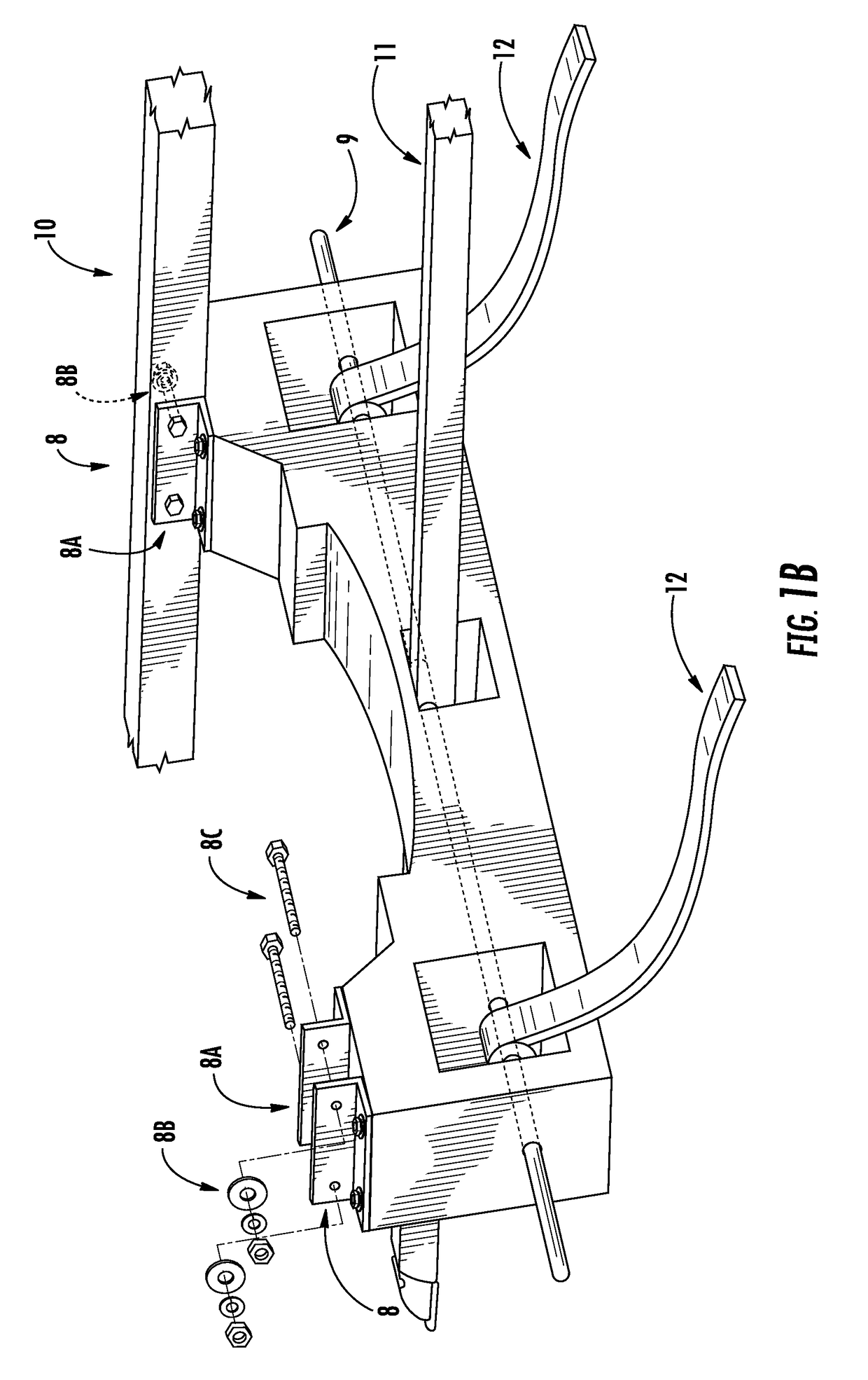
[0061]a second connector device having a first and a second leaf spring attached thereto such that the leaf springs float freely in a first and second cavity in the f

Problems solved by technology

With all of these design choices, however, one of the problems with current industry standards is that the trailer once completed is a device designed for a discrete use.
Because of this a user has to spend a considerable sum of money to have a device that is used only for one type of service.
This leaves no option for easily transferring items from one type of trailer system to another as the boat type of trailer does not lend itself to taking a motorcycle or vice versa.
Another problem with trailers today is that steel or galvanized steel materials utilized in their construction easily corrode when exposed to the elements during ordinary use.
The imm

Method used


Image

  • Structural cross frame connector and system
  • Structural cross frame connector and system
  • Structural cross frame connector and system

Examples


Embodiment Construction

[0082]The following detailed description is merely exemplary in nature and is not intended to limit the described embodiments or the application and uses of the described embodiments. As used herein, the word “exemplary” or “illustrative” means “serving as an example, instance, or illustration.” Any implementation described herein as “exemplary” or “illustrative” is not necessarily to be construed as preferred or advantageous over other implementations. All of the implementations described below are exemplary implementations provided to enable persons skilled in the art to make or use the embodiments of the disclosure and are not intended to limit the scope of the disclosure, which is defined by the claims. For purposes of description herein, the terms “upper”, “lower”, “left”, “rear”, “right”, “front”, “vertical”, “horizontal”, and derivatives thereof shall relate to the invention as oriented in each figure.

[0083]Furthermore, there is no intention to be bound by any expressed or impli


PUM


Abstract

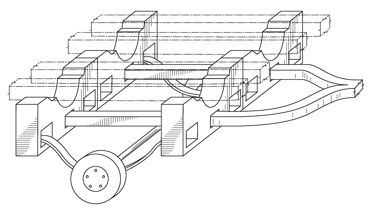
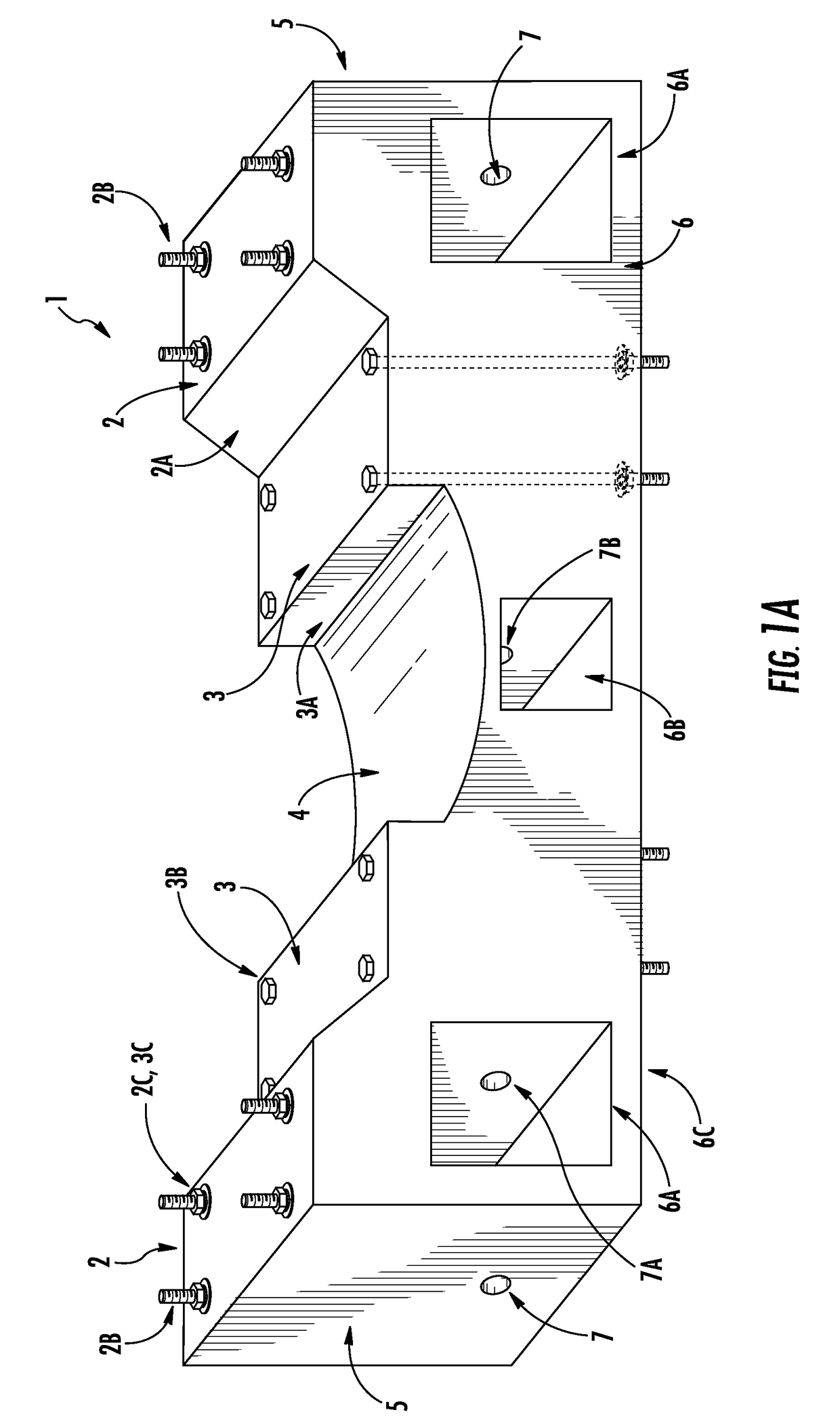
A structural cross frame connector is described having a multipurpose system of attachment. The device has two main forms one with a vertical offset and one without this vertical offset. The central portion has an arch by which weight is distributed accordingly. The connectors have a a group of pass through holes whereby a pass through rod is attached thereto using fasteners. Various structural members can be attached to the pass through rod using pass right and left pass through cavities typically used as structural support members and a central pass through cavity typically used as a hitching station. Leaf springs are also mountable on pass through rods and freely operate on another connector right and left pass through cavity for use as a suspension system.

Description


Claims


Application Information

Patent Timeline
Owner PINCHEON JEFFREY R
Why Eureka
Try Eureka