A hydraulic system and a method for moving an implement of a working machine

Active Publication Date: 2018-08-16
VOLVO CONSTR EQUIP
View PDF3 Cites 2 Cited by
  • Summary
  • Abstract
  • Description
  • Claims
  • Application Information

AI Technical Summary

Benefits of technology

[0049]Preferably, the method comprises determining whether the pressure at the hydraulic accumulator is at least as high as the pressure at the first port, and the step of determining whether to provide a free fluid communication between the hydraulic accumulator and the first port, is based on said determination whether the pressure at the hydraulic accumulator is at least as high as the pressure at the first port. Thereby, movements of the implement due to a pressure difference between the hydraulic accumulator and the first port, at engagement of the hydraulic accumulator to the first port, can be avoided.
[0050]Preferably, the method comprises providing the free fluid communicatio

Problems solved by technology

With increasing demands for more energy efficient working machines, traditional systems for powering the hydraulic cylinders present certain problems.
However, using the same pump for actuation and hydraulic accumulator charging will create a lack of accuracy in the hydraulic cylinder control.
The reason is that the direct proportionality of the rate of movement of the piston

Method used


Image

  • A hydraulic system and a method for moving an implement of a working machine
  • A hydraulic system and a method for moving an implement of a working machine
  • A hydraulic system and a method for moving an implement of a working machine

Examples


Embodiment Construction

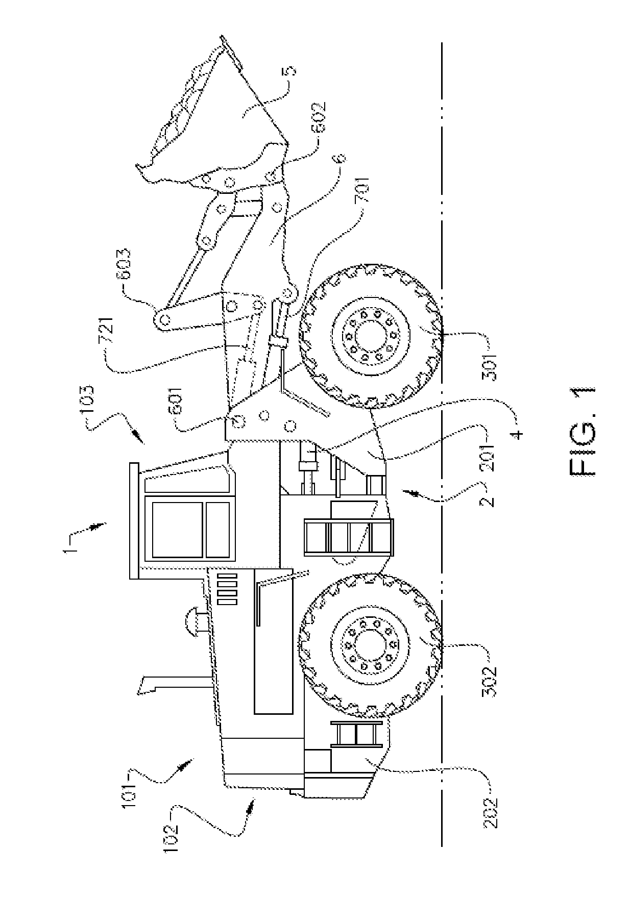
[0073]FIG. 1 is an illustration of a working machine 1 in the form of a wheel loader. The wheel loader is an example of a working machine where a hydraulic system according to the invention can be applied.

[0074]The wheel loader comprises a body structure 2 with a front body part 201 and a rear body part 202 presenting two front wheels 301 and two rear wheels 302, respectively. Two steering hydraulic cylinders 4 are arranged on opposite sides of the wheel loader 1 for turning the wheel loader by means of relative movement of the front body part 201 and the rear body part 202. In other words, the wheel loader 1 is articulated and frame steered by means of the steering hydraulic cylinders 4. There is a pivot joint connecting the front body part 201 and the rear body part 202 of the wheel loader 1 such that these parts are pivotally connected to each other for pivoting about a substantially vertical axis.

[0075]The rear body part 202 of the wheel loader 1 comprises an engine compartment 101


PUM


Abstract

A hydraulic system for moving an implement of a working machine includes a hydraulic cylinder with a cylinder and a piston which is adapted to move in the cylinder to thereby move the implement relative to a body structure of the working machine, and an actuator pump arranged to provide hydraulic fluid to the hydraulic cylinder, the hydraulic cylinder having a first port and a second port adapted to be in fluid communication with the actuator pump, the hydraulic cylinder and the actuator pump being arranged so that the hydraulic cylinder is directly controlled by the actuator pump so that the rate of movement of the piston of the hydraulic cylinder is purely pump controlled, the hydraulic system further including a hydraulic accumulator for suspension of the implement, which hydraulic accumulator is arranged to be selectively connectable to the first port, the hydraulic system further including a further pump in addition to the actuator pump, the hydraulic accumulator being arranged to be pressurised by the further pump.

Description


Claims


Application Information

Patent Timeline
Owner VOLVO CONSTR EQUIP
Why Eureka
Try Eureka