Squeeze film damper bearing device
a technology of damper bearing and squeeze film, which is applied in the direction of elastic bearings, rigid support of bearing units, machines/engines, etc., can solve the problems of increasing dimensions and weight, and achieve the effect of simple structur
- Summary
- Abstract
- Description
- Claims
- Application Information
AI Technical Summary
Benefits of technology
Problems solved by technology
Method used
Image

Examples
first embodiment
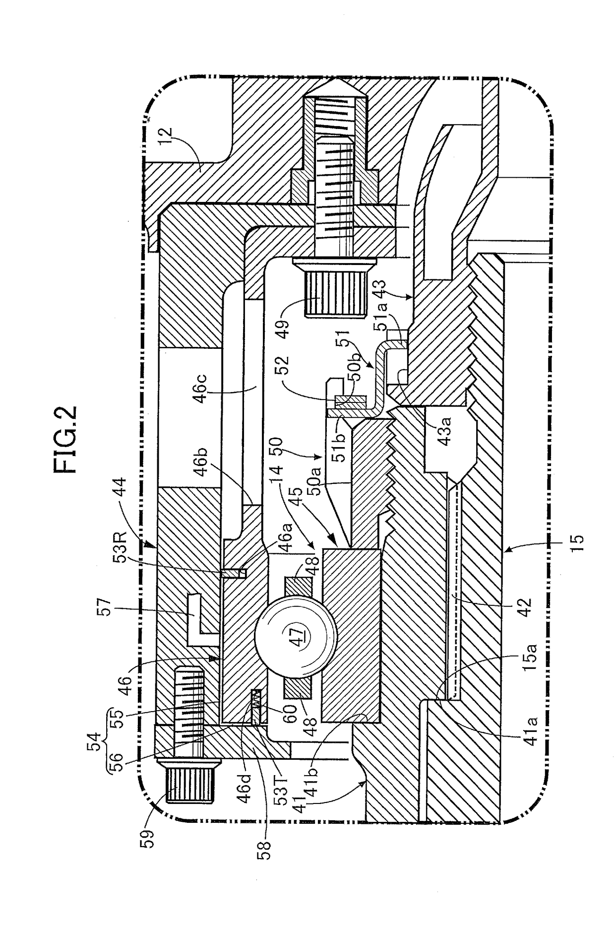
[0020]A first embodiment of the present invention is explained below based on FIGS. 1 and 2.
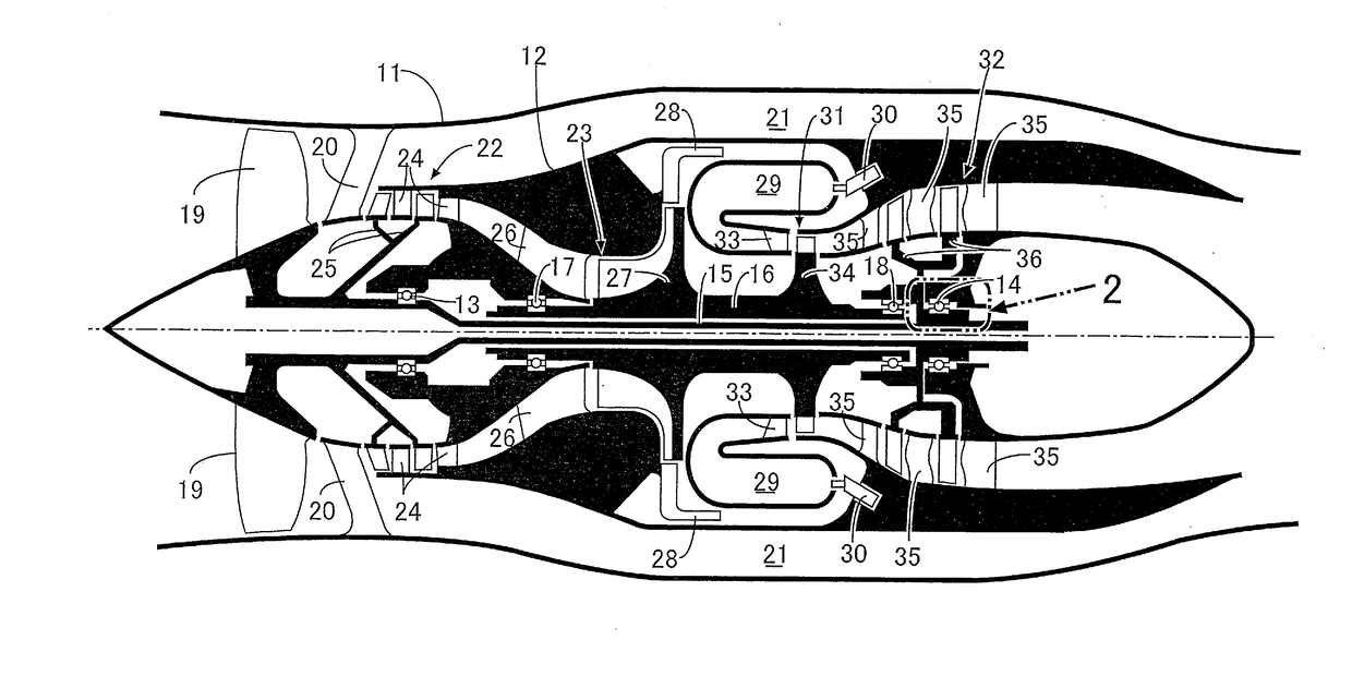
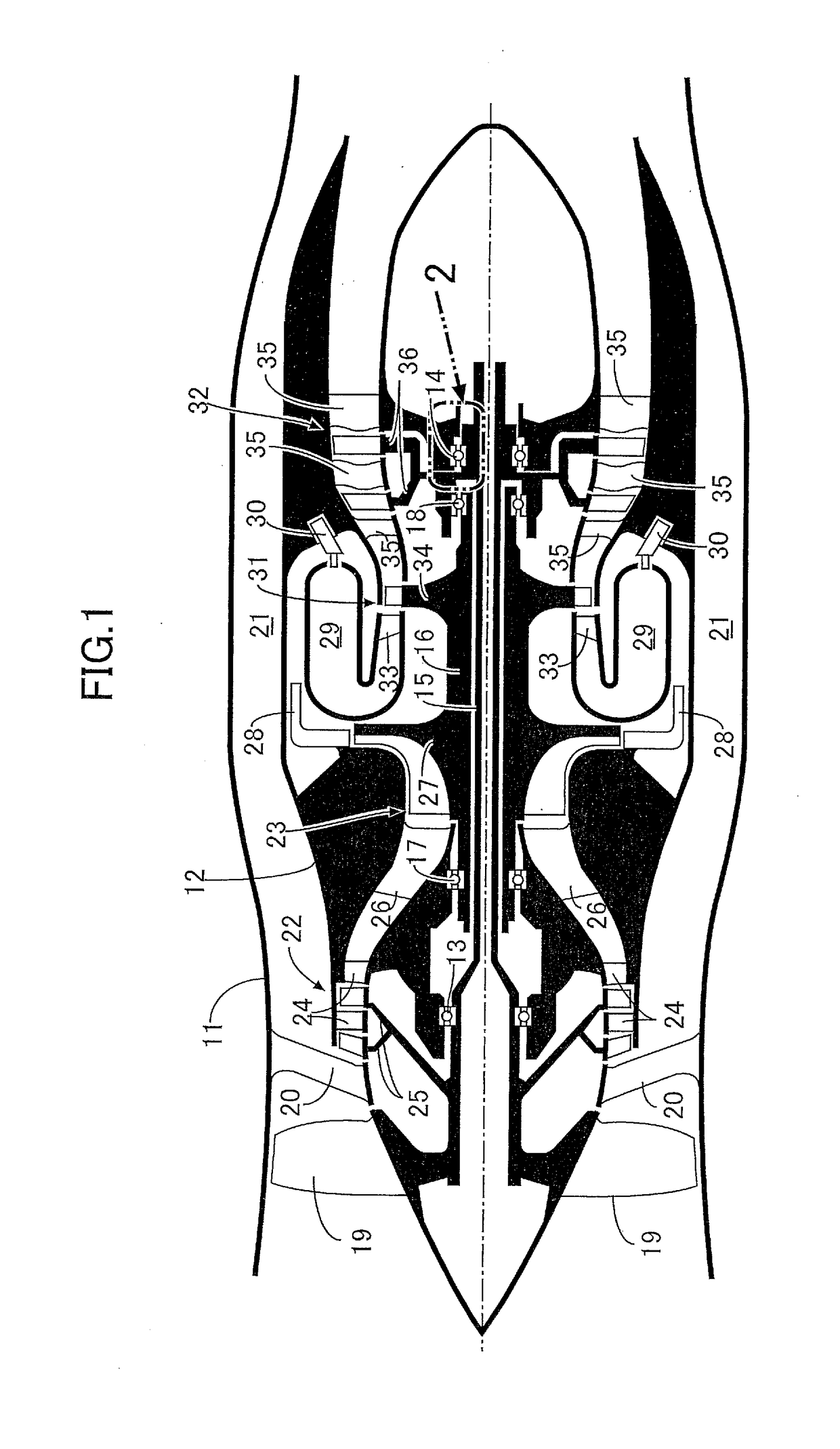
[0021]As shown in FIG. 1, a gas turbine engine for an aircraft to which the present invention is applied includes an outer casing 11 and an inner casing 12, and a front part and a rear part of a low pressure system shaft 15 are rotatably supported in the interior of the inner casing 12 via a front first bearing 13 and a rear first bearing 14, respectively. A tubular high pressure system shaft 16 is relatively rotatably fitted around the outer periphery of an intermediate part in the axial direction of the low pressure system shaft 15, a front part of the high pressure system shaft 16 is rotatably supported on the inner casing 12 via a front second bearing 17, and a rear part of the high pressure system shaft 16 is relatively rotatably supported on the low pressure system shaft 15 via a rear second bearing 18.
[0022]A front fan 19 is fixed to the front end of the low pressure system shaft 15, blad
second embodiment
[0046]A second embodiment of the present invention is now explained with reference to FIG. 3.
[0047]In the second embodiment, the outer race 46 is detached from the bearing retaining member 44 and the inner casing 12 and is completely floatingly supported, and a flange 44a projecting radially inward from the inner periphery of the bearing retaining member 44 opposes the other end face in the axial direction of the outer race 46. That is, a pair of annular second spaces 56 sealed by seal rings 53T are defined on opposite end faces in the axial direction of the outer race 46, and the seal ring 53R on the outer periphery of the outer race 46 of the first embodiment is eliminated.
[0048]In accordance with this embodiment, in addition to the effects of the first embodiment, due to the squeeze films being formed on opposite sides in the axial direction of the outer race 46, the effect in damping vibration in the axial direction of the low pressure system shaft 15 can be further enhanced.
third embodiment
[0049]A third embodiment of the present invention is now explained by reference to FIG. 4.
[0050]The third embodiment is a modification of the first embodiment, and an intermediate seal ring 61 is provided on the outer periphery of the outer race 46 close to the border between the first space 55 and the second space 56. Therefore, the first space 55 is defined by the seal ring 53R and the intermediate seal ring 61, oil is supplied thereto via an oil passage 57R, the second space 56 is defined by the seal ring 53T and the intermediate seal ring 61, and oil is supplied thereto via an oil passage 57T.
[0051]In accordance with this embodiment, by individually controlling the pressure and temperature of oil supplied to the first space 55 and the second space 56, the damping force in the radial direction due to the squeeze film of the first space 55 and the damping force in the axial direction due to the squeeze film of the second space 56 can be independently adjusted.
[0052]Embodiments of the
PUM
 Abstract
Description
Claims
Application Information
 - R&D Engineer
- R&D Manager
- IP Professional
- Industry Leading Data Capabilities
- Powerful AI technology
- Patent DNA Extraction
Browse by: Latest US Patents, China's latest patents, Technical Efficacy Thesaurus, Application Domain, Technology Topic.
© 2024 PatSnap. All rights reserved.Legal|Privacy policy|Modern Slavery Act Transparency Statement|Sitemap